

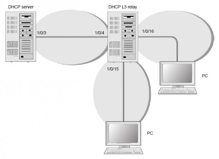
The following figure and procedure show how you can use a NETGEAR fully managed switch to configure a DHCP pool to assign IP addresses to DHCP clients. For information about configuring a DHCP L3 relay, see How do I configure a DHCP L3 relay using the device UI on my fully managed switch? or How do I configure a DHCP L3 relay using CLI commands on my fully managed switch?
This procedure describes how to make port 1/0/3 a routing interface with RIP enabled, create a DHCP pool with the name dhcp_server, and create a second DHCP pool with the name dhcp_server_second. This procedure also excludes IP addresses 10.200.1.1 and 10.200.2.1 from the DHCP global configuration because these two IP addresses are already used for the DHCP L3 relay (for more information, see the previously mentioned articles).
To configure a DHCP pool to assign IP addresses to DHCP clients:
Step 1. Log in to the fully managed switch:
- Launch a web browser and enter the IP address of the switch in the address field of your web browser.
The login page displays. - Click the Main UI Login button.
The main UI login page displays in a new tab. - Enter admin as the user name and enter one of the following passwords:
- Enter your local device password.
The first time that you log in, no password is required. However, you then must specify
a local device password to use each subsequent time that you log in. - If you are managing the switch through the Engage controller, enter the site password
for the Engage site to which the switch is onboarded. - If, in addition to the main UI, you are also managing the switch through the Insight Cloud Portal
or Insight app, enter the Insight network password for the Insight network to which the switch is added.
- Click the Login button.
The System Information page displays.
Step 2. Enable routing mode on the switch:
- Select Routing > IP > Basic > IP Configuration.
The IP Configuration page displays. - Select the Routing Mode Enable radio button.
- Click the Apply button.
Your settings are saved.
Step 3. Create a routing interface and assign IP address 10.100.1.1/24 to the interface:
- Select Routing > IP > Advanced > IP Interface Configuration.
The IP Interface Configuration page displays. - Select the 1/0/3 check box.
- From the IP Address Configuration Method menu, select Manual.
- In the IP Address field, enter 10.100.1.1.
- In the Subnet Mask field, enter 255.255.255.0.
- From the Routing Mode menu, select Enable.
- Click the Apply button.
Your settings are saved.
Step 4. Enable RIP on interface 1/0/3:
- Select Routing > RIP > Advanced > Interface Configuration.
The Interface Configuration page displays. - In the Interface field, select 1/0/3.
- From the RIP Mode menu, select Enable.
- Click the Apply button.
Your settings are saved.
Step 5. Configure the DHCP global configuration and exclude IP addresses
10.200.1.1 and 10.200.2.1 from the DHCP pool:
- Select System > Services > DHCP Server > DHCP Server Configuration.
The DHCP Server Configuration page displays. - Select the Admin Mode Enable radio button.
- In the IP Range From field, enter 10.200.1.1.
- In the IP Range To field, enter 10.200.1.1.
This IP address is already used for the DHCP L3 relay. - Click the Add button.
Your settings are saved. - In the IP Range From field, enter 10.200.2.1.
Also this IP address is already used for the DHCP L3 relay. - In the IP Range To field, enter 10.200.2.1.
- Click the Add button.
Your settings are saved.
Step 6. Create a DHCP pool with the name dhcp_server:
- Select System > Services > DHCP Server > DHCP Pool Configuration.
The DHCP Pool Configuration page displays. - From the Pool Name menu, select Create.
- In the Pool Name field, enter dhcp_server.
- From the Type of Binding menu, select Dynamic.
- In the Network Address field, enter 10.200.1.0.
- In the Network Mask field, enter 255.255.255.0.
As an alternate, you can enter 24 in the Network Prefix Length field. Do not specify both
the network mask and the network prefix length. - Click the Add button.
The dhcp-server name is added to the Pool Name menu.
Step 7. Create a DHCP pool with the name dhcp_server_second:
- Select System > Services > DHCP Server > DHCP Pool Configuration.
The DHCP Pool Configuration page displays. - From the Pool Name menu, select Create.
- In the Pool Name field, enter dhcp_server_second.
- From the Type of Binding menu, select Dynamic.
- In the Network Address field, enter 10.200.2.0.
- In the Network Mask field, enter 255.255.255.0.
As an alternate, you can enter 24 in the Network Prefix Length field. Do not specify both
the network mask and the network prefix length. - Click the Add button.
The dhcp-server_second name is added to the Pool Name menu.
For information about using the CLI, see How do I configure a DHCP server using CLI commands on my fully managed switch?