

Front Panel
The following figure shows the front panel of the ReadyDATA 5200 with the optional front bezel removed:
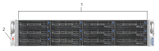
1. Drive bays with disk status LEDs
2. Control panel
The following figure shows the control panel in more detail:
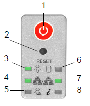
1. Power button
2. Reset button
3. Power LED
4. Ethernet LED
5. Power diagnostic LED
6. Disk activity LED
7. Ethernet LED
8. Information LED
Each drive bay features a latch that releases the pop-out tray handle, as shown in the following figure:
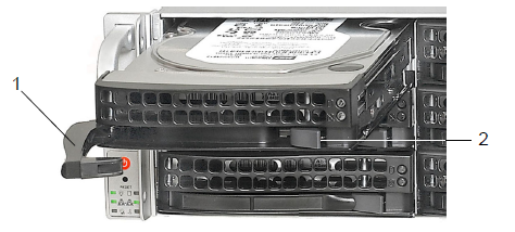
1. Disk tray handle
2. Disk tray release latch
WARNING: No matter how many hard drives are installed in your system, ensure that all drive trays remain in the drive bays to maintain proper airflow.
For more information about adding and replacing disk drives, see the following support articles:
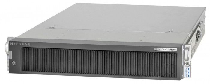
The ReadyDATA 5200 comes with an front bezel that protects the drive bays with a lockable cover. You can operate the ReadyDATA 5200 with or without the front bezel.
The following image shows a ReadyDATA 5200 with the front bezel installed:
For more information about installing and removing the front bezel, see the How do I install the front bezel on my ReadyDATA 5200?
Rear Panel
The following figure shows the rear panel of the ReadyDATA 5200:
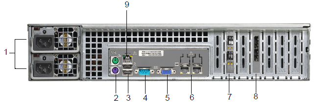
1. Power supplies
2. PS2 keyboard and mouse ports
3. USB ports
4. RS232 console port
5. VGA monitor port
6. 1-gigabit Ethernet ports with status LED status indicators
7. 10-gigabit Ethernet ports with status LED status indicators
8. SAS output port
9. Maintenance port