

- Create a DHCP pool:
Note: This article assumes that the DHCP service is enabled. For information see the How do I configure a Dynamic Host Configuration Protocol (DHCP) server in dynamic mode using the web interface on my managed switch? support article.
- Select System > Services > DHCP Server > DHCP Server Configuration.
A screen similar to the following displays.
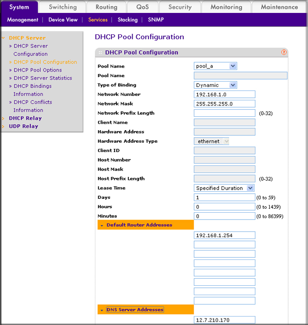
- Under DHCP Pool Configuration, enter the following information:
- In the Pool Name field, select Create.
- In the Pool Name field, enter pool-a.
- In the Type of Binding field, select Dynamic.
- In the Network Number field, enter 192.168.1.0.
- In the Network Mask field, enter 255.255.255.0.
- In the Days field, enter 1.
- Click Default Router Addresses. The DNS server address fields display. In the first Router Address field, enter 192.168.1.254.
- Click DNS Server Addresses. The router address fields display. In the first DNS Server Address field, enter 12.7.210.170.
- Click Add.
- Select System > Services > DHCP Server > DHCP Server Configuration.
- Configure a VLAN and include ports 1/0/23 and 1/0/24 in the VLAN:
- Select Routing > VLAN > VLAN Routing Wizard.
A screen similar to the following displays.

- Enter the following information:
- In the Vlan ID field, enter 192.
- In the IP Address field, enter 192.168.1.254.
- In the Network Mask field, enter 255.255.255.0.
- Click Unit 1. The ports display:
- Click the gray box under port 23 twice until U displays.
- Click the gray box under port 24 twice until U displays.
- Click Apply to save the VLAN that includes ports 23 and 24.
- Select Routing > VLAN > VLAN Routing Wizard.
- Configure a VLAN and include port 1/0/48 in the VLAN:
- Select Routing > VLAN > VLAN Routing Wizard.
A screen similar to the following displays.
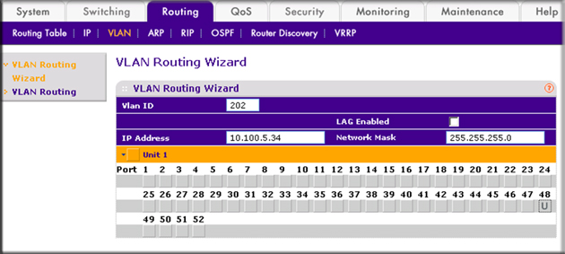
- Enter the following information:
- In the Vlan ID field, enter 202.
- In the IP Address field, enter 10.100.5.34.
- In the Network Mask field, enter 255.255.255.0.
- Click Unit 1. The ports display:
- Click the gray box under port 48 twice until U displays. The U specifies that the egress packet is untagged for the port.
- Click Apply to save the VLAN that includes port 48.
- Select Routing > VLAN > VLAN Routing Wizard.
- Enable IP routing:
- Select Routing > IP > Basic > IP Configuration.
A screen similar to the following displays.
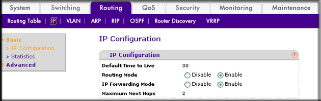
- Under IP Configuration, make the following selections:
- For Routing Mode, select the Enable radio button.
- For IP Forwarding Mode, select the Enable radio button.
- Click Apply to enable IP routing.
- Select Routing > IP > Basic > IP Configuration.
- Configure default route for VLAN 202:
- Select Routing > Routing Table > Basic > Route Configuration.
A screen similar to the following displays.
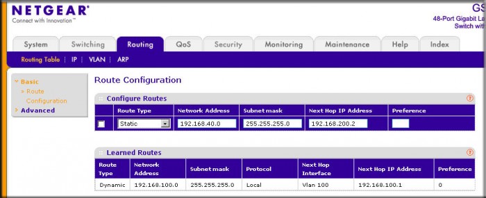
- Under Configure Routes, in the Route Type list, select Default Route.
- In the Next Hop IP Address field, enter 10.100.5.252.
- Click Add to add the route that is associated to VLAN 202 to the Learned Routes table.
- Select Routing > Routing Table > Basic > Route Configuration.
- Configure port 23 and port 24 as protected ports:
- Select Security > Traffic Control > Protected Port.
A screen similar to the following displays.
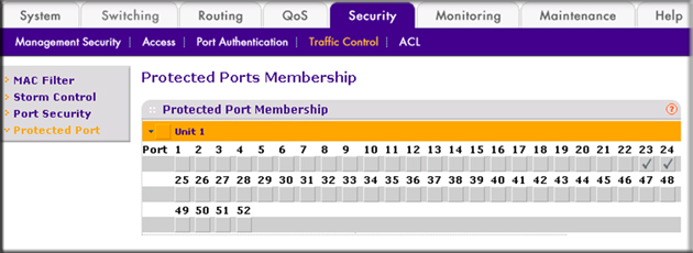
- Under Protected Ports Configuration, click Unit 1. The ports display.
- Click the gray box under port 23. A check mark displays in the box.
- Click the gray box under port 24. A check mark displays in the box.
- Click Apply to activate ports 23 and 24 as protected ports.
- Select Security > Traffic Control > Protected Port.
For more information, see tge following support articles:
- What are protected ports and how do they work with my managed switch?
- How do I configure a protected port to isolate ports using CLI commands on my managed switch?
This article applies to the following managed switches and their respective firmware:
- M5300 - firmware version 10.0.0.x
-
- M5300-28G (GSM7228S)
- M5300-5G (GSM7252S)
- M5300-28G3 (GSM7328Sv2h2)
- M5300-52G3 (GSM7352Sv2h2)
- M5300-28G_POE+ (GSM7228PSv1h2)
- M5300-52G-POE+ (GSM7252PSv1h2)
- M5300-28GF3 (GSM7328FSv2)
- M4100 - firmware version 10.0.1.x
-
- M4100-26G (GSM7224v2h2)
- M4100-50G (GSM7248v2h2)
- M4100-26G-POE (GSM7226Pv1h1)
- M4100-50G-POE+ (GSM7248Pv1h1)
- M4100-26G-POE (FSM7226Pv1h1)
- M4100-50-POE (FSM7250Pv1h1)
- M4100-D12G (GSM5212v1h1)
- M4100-D10-POE (FSM5210Pv1h1)
- M7100 - firmware version 10.0.1.x
-
- M7100-24X (XSM7224)
- XSM7224S - firmware version 9.0.1.x
Last Updated:07/07/2025
|
Article ID: 21795