

This example shows how to isolate VLANs on a Layer 3 switch by using ACLs. In this example, PC 1 is in VLAN 24, PC 2 is in VLAN 48, and the server is in VLAN 38. PC 1 and PC 2 are isolated by an ACL but can both access the server.
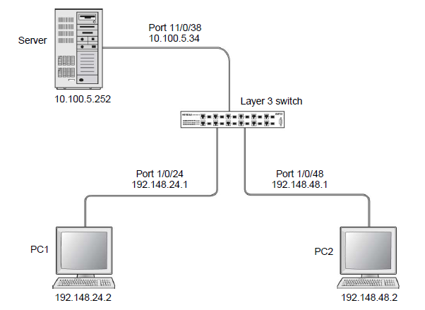
- Create VLAN 24 with IP address 192.168.24.1.
- Select Routing > VLAN > VLAN Routing Wizard.
A screen similar to the following displays.
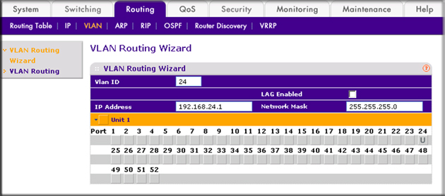
- Enter the following information:
- In the Vlan ID field, enter 24.
- In the IP Address field, enter 192.168.24.1.
- In the Network Mask field, enter 255.255.255.0.
- Click Unit 1.
The ports display.
- Click the gray box under port 24 twice until U displays.
The U specifies that the egress packet is untagged for the port.
- Click Apply to save VLAN 24.
- Select Routing > VLAN > VLAN Routing Wizard.
- Create VLAN 48 with IP address 192.168.48.1.
- Select Routing > VLAN > VLAN Routing Wizard.
A screen similar to the following displays.
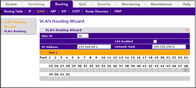
- Enter the following information:
- In the Vlan ID field, enter 48.
- In the IP Address field, enter 192.168.48.1.
- In the Network Mask field, enter 255.255.255.0.
- Click Unit 1.
The ports display.
- Click the gray box under port 48 twice until U displays.
The U specifies that the egress packet is untagged for the port.
- Click Apply to save VLAN 48.
- Select Routing > VLAN > VLAN Routing Wizard.
- Create VLAN 38 with IP address 10.100.5.34.
- Select Routing > VLAN > VLAN Routing Wizard.
A screen similar to the following displays.
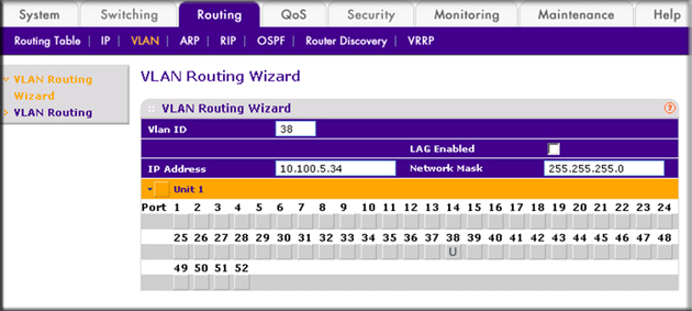
- Enter the following information in the VLAN Routing Wizard:
- In the Vlan ID field, enter 38.
- In the IP Address field, enter 10.100.5.34.
- In the Network Mask field, enter 255.255.255.0.
- Click Unit 1. The ports display.
- Click the gray box under port 38 twice until U displays.
The U specifies that the egress packet is untagged for the port.
- Click Apply to save VLAN 38.
- Select Routing > VLAN > VLAN Routing Wizard.
- Enable IP routing:
- Select Routing > IP > Basic > IP Configuration.
A screen similar to the following displays.
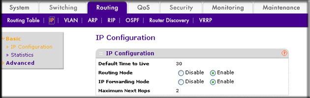
- Under IP Configuration, make the following selections:
- For Routing Mode, select the Enable radio button.
- For IP Forwarding Mode, select the Enable radio button.
- Click Apply to enable IP routing.
- Select Routing > IP > Basic > IP Configuration.
- Create an ACL with ID 101.
- Select Security > ACL > Advanced > IP ACL.
A screen similar to the following displays.
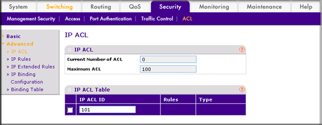
- In the IP ACL Table, in the IP ACL ID field, enter 101.
- Click Add.
- Select Security > ACL > Advanced > IP ACL.
- Create an ACL with ID 102.
- Select Security > ACL > Advanced > IP ACL.
A screen similar to the following displays.
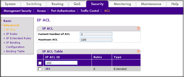
- In the IP ACL Table, in the IP ACL ID field, enter 102.
- Click Add.
- Select Security > ACL > Advanced > IP ACL.
- Create an ACL with ID 103.
- Select Security > ACL > Advanced > IP ACL.
A screen similar to the following displays.
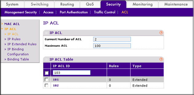
- In the IP ACL ID field of the IP ACL Table, enter 103.
- Click Add.
- Select Security > ACL > Advanced > IP ACL.
- Add and configure an IP extended rule that is associated with ACL 101:
- Select Security > ACL > Advanced > IP Extended Rules.
A screen similar to the following displays.
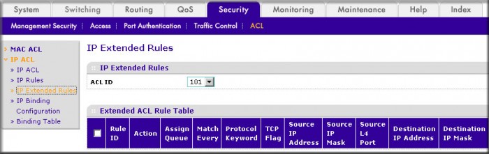
- Under IP Extended Rules, in the ACL ID field, select 101.
- Click Add.
The Extended ACL Rule Configuration screen displays.

- Under Extended ACL Rule Configuration (100-199), enter the following information and make the following selections:
- In the Rule ID field, enter 1.
- For Action, select the Deny radio button.
- In the Match Every field, select False.
- In the Destination IP Address field, enter 192.168.24.0.
- In the Destination IP Mask field, enter 0.0.0.255.
- Click Apply to save the settings.
- Select Security > ACL > Advanced > IP Extended Rules.
- Add and configure an IP extended rule that is associated with ACL 102.
- Select Security > ACL > Advanced > IP Extended Rules.
A screen similar to the following displays.
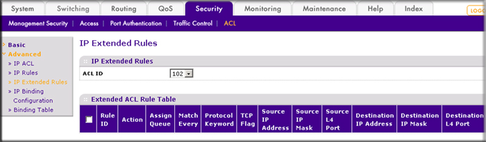
- Under IP Extended Rules, in the ACL ID field, select 102.
- Click Add.
The Extended ACL Rule Configuration screen displays.
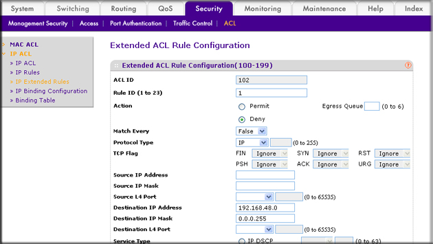
- Under Extended ACL Rule Configuration (100-199), enter the following information and make the following selections:
- In the Rule ID field, enter 1.
- For Action mode, select the Deny radio button.
- In the Match Every field, select False.
- In the Destination IP Address field, enter 192.168.48.0.
- In the Destination IP Mask field, enter 0.0.0.255.
- Click Apply to save the settings.
- Select Security > ACL > Advanced > IP Extended Rules.
- Add and configure an IP extended rule that is associated with ACL 103:
- Select Security > ACL > Advanced > IP Extended Rules.
A screen similar to the following displays.
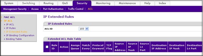
- Under IP Extended Rules, in the ACL ID field, select 103.
- Click Add.
The Extended ACL Rule Configuration screen displays.
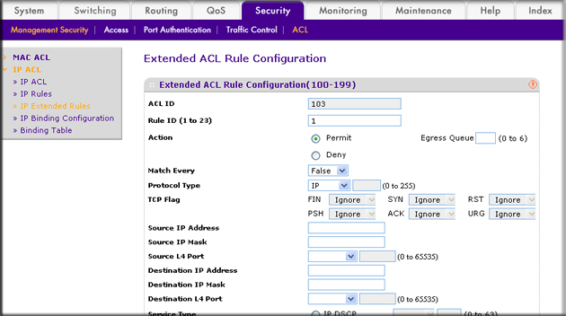
- Under Extended ACL Rule Configuration (100-199), enter the following information and make the following selections:
- In the Rule ID field, enter 1.
- For Action mode, select the Permit radio button.
- In the Match Every field, select False.
- In the Protocol Type field, select IP.
- Click Apply to save the settings.
- Select Security > ACL > Advanced > IP Extended Rules.
- Apply ACL 102 to port 24:
- Select Security > ACL > Advanced > IP Binding Configuration.
A screen similar to the following displays.

- Under Binding Configuration, make the following selection and enter the following information:
- In the ACL ID field, select 102.
- In the Sequence Number field, enter 1.
- Click Unit 1. The ports display.
- Click the gray box under port 24. A check mark displays in the box.
- Click Apply to save the settings.
- Select Security > ACL > Advanced > IP Binding Configuration.
- Apply ACL 101 to port 48:
- Select Security > ACL > Advanced > IP Binding Configuration.
A screen similar to the following displays.
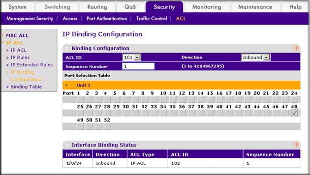
- Under Binding Configuration, make the following selection and enter the following information:
- In he ACL ID field, select 101.
- In the Sequence Number field, enter 1.
- Click Unit 1.
The ports display.
- Click the gray box under port 48.
A check mark displays in the box.
- Click Apply to save the settings.
- Select Security > ACL > Advanced > IP Binding Configuration.
- Apply ACL 103 to port 24 and port 48:
- Select Security > ACL > Advanced > IP Binding Configuration.
A screen similar to the following displays.
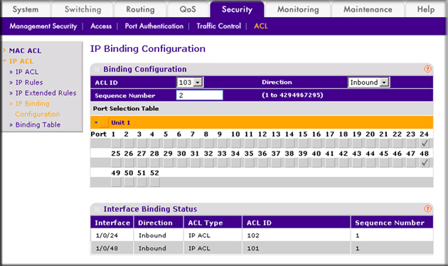
- Under Binding Configuration, make the following selection and enter the following information:
- In the ACL ID field, select 103.
- In the Sequence Number field, enter 2.
- Click Unit 1.
The ports display. Configure the following ports:- Click the gray box under port 24. A check mark displays in the box.
- Click the gray box under port 48. A check mark displays in the box.
- Click Apply to save the settings.
- Select Security > ACL > Advanced > IP Binding Configuration.
For more information, see the following support articles:
- What are Access Control Lists (ACLs) and how do they work with my managed switch?
- How do I use CLI commands on my managed switch to configure one-way access using a TCP Flag in Access Control List (ACL)?
This article applies to the following managed switches and their respective firmware:
- M5300 - firmware version 10.0.0.x
-
- M5300-28G (GSM7228S)
- M5300-5G (GSM7252S)
- M5300-28G3 (GSM7328Sv2h2)
- M5300-52G3 (GSM7352Sv2h2)
- M5300-28G_POE+ (GSM7228PSv1h2)
- M5300-52G-POE+ (GSM7252PSv1h2)
- M5300-28GF3 (GSM7328FSv2)
- M4100 - firmware version 10.0.1.x
-
- M4100-26G (GSM7224v2h2)
- M4100-50G (GSM7248v2h2)
- M4100-26G-POE (GSM7226Pv1h1)
- M4100-50G-POE+ (GSM7248Pv1h1)
- M4100-26G-POE (FSM7226Pv1h1)
- M4100-50-POE (FSM7250Pv1h1)
- M4100-D12G (GSM5212v1h1)
- M4100-D10-POE (FSM5210Pv1h1)
- M7100 - firmware version 10.0.1.x
-
- M7100-24X (XSM7224)
- XSM7224S - firmware version 9.0.1.x
Last Updated:07/07/2025
|
Article ID: 21720