

This article describes how to configure two NETGEAR Smart Switches with traditional UIs to exchange traffic for multiple VLANs.
In this example, each switch is configured with two VLANs (VLAN 10 and VLAN 20). There is a link between the switches over which traffic for both VLANs can pass. We call this link the VLAN Trunk Link.
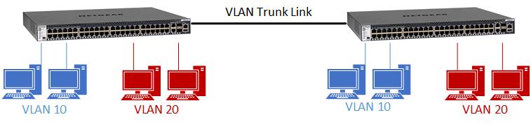
In this example, the VLAN port membership on each switch is the same. We are therefore applying the same configuration to each switch.
- Ports 1 - 5: VLAN 10
- Ports 6 - 10: VLAN 20
- Port 20: VLAN Trunk Link
To set up a VLAN trunk link between two NETGEAR Smart Switches with traditional UIs:
Steps 1 through 4 must be followed on each Smart Switch.
Step 1. Log in to the Smart Switch:
- Connect your computer to the same network as the switch.
You can use a WiFi or wired connection to connect your computer to the network, or
connect directly to a switch that is off-network using an Ethernet cable. - Launch a web browser.
- In the address field of your web browser, enter the IP address of the switch.
If you do not know the IP address, see How do I discover a NETGEAR Smart Switch.
The Device UI login page displays. - Enter one of the following passwords:
- Enter your device admin password.
- If you previously managed the switch through the Insight app or Cloud portal,
enter the Insight network password for the last Insight network location.
- Click the Go button.
The System Information page displays.
Step 2. Create VLAN 10 and VLAN 20:
- Select Switching > VLAN > Basic > VLAN Configuration.
The VLAN Configuration page displays. - In the VLAN ID field, type 10.
- Click the Add button.
Your settings are saved. - In the VLAN ID field, type 20.
- Click the Add button.
Your settings are saved.
Step 3. Add ports to VLAN 10 and VLAN 20 and remove ports from VLAN 1:
- Select Switching > VLAN > Advanced > VLAN Membership.
The VLAN Membership page displays. - From the VLAN ID menu, select 10.
- Click ports 1, 2, 3, 4, and 5 until a U displays.
The selected ports are added as untagged members of VLAN 10. Untagged ports connect to client devices such as computers. - Click port 20 until a T displays.
The selected port is added as a tagged member of VLAN 10. A tagged port is used as a VLAN trunk link. - Click the Apply button.
Your settings are saved. - From the VLAN ID menu, select 20.
- Click ports 6, 7, 8, 9, and 10 until a U displays.
The selected ports are added as untagged members of VLAN 20. - Click port 20 until a T displays.
The selected port is added as a tagged member of VLAN 20. - Click the Apply button.
Your settings are saved. - From the VLAN ID menu, select 1.
- Remove ports 1, 2, 3, 4, 5, 6 , 7, 8, 9, and 10 from VLAN 1 by clicking each port until it is blank (that is,
neither a U or a T displays).
Note: By default, VLAN 1 is the management VLAN. Be careful not to remove the port you are managing the switch
through from the management VLAN! - Click the Apply button.
Your settings are saved.
Step 4. Configure port PVID settings for untagged ports:
For each port that you marked as untagged in Step 3, we are setting the PVID of that port to the ID of the VLAN it was
assigned to.
- Select Switching > VLAN > Advanced > Port PVID Configuration.
The PVID Configuration page displays. - Select the check boxes for ports 1, 2, 3, 4, and 5.
- In the PVID field, type 10.
VLAN 10 is assigned as the PVID for the selected ports. - Click the Apply button.
Your settings are saved. - Select the check boxes for ports 6, 7, 8, 9, and 10.
- In the PVID field, type 20.
VLAN 20 is assigned as the PVID for the selected ports. - Click the Apply button.
Your settings are saved.
Step 5. Connect the switches:
- Connect both switches using port 20 on each switch.
- To confirm that the configuration is successful, verify that a computer in VLAN 10 on one switch can communicate with a computer in VLAN 10 on the second switch.