

Smart switches support only one type of Quality of Service (QoS): Differentiated Services (DiffServ). For information about QoS, see the “What is Quality of Service
To create a DiffServ class and policy, and attach the policy to a switch interface:
- Open a web browser.
- In the browser address field, type the IP address of the smart switch.
The default IP address is 192.168.0.239 and the default subnet mask is 255.255.255.0.
You are prompted to enter your password.
- Type the password in the Password field.
The default password is password. Passwords are case-sensitive.
- Click the Login button.
After the system authenticates you, the System Information screen displays.
- Select QoS>DiffServ>Advanced>Class Configuration.
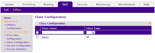
- Create a new class with the following settings:
- Class Name. class1.
- Class Type. All.
- Click the Add button.
The new policy is added.
- Click the class1 hyperlink.
The DiffServ Class Configuration screen for class1 displays.

- Configure the following settings for class1:
- Protocol Type. UDP.
- Source IP Address. 192.12.1.0.
- Source Mask. 255.255.255.0.
- Source L4 Port. Other, and enter 4567 as the source port value.
- Destination IP Address. 192.12.2.0.
- Destination Mask. 255.255.255.0.
- Destination L4 Port. Other, and enter 4568 as the destination port value.
- Click the Apply button.
The settings are saved and the Policy Configuration screen displays again.
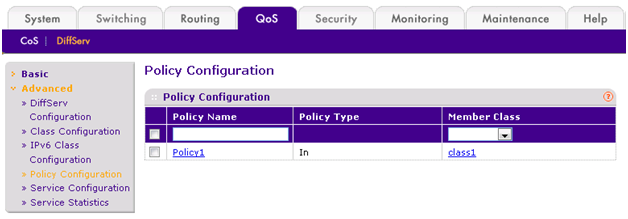
- On the Policy Configuration screen, create a new policy with the following settings:
- Policy Selector. Policy1.
- Member Class. class1.
- Click the Add button.
The new policy is added.
- Click the Policy1 hyperlink.
The Policy Class Configuration screen displays for Policy1.
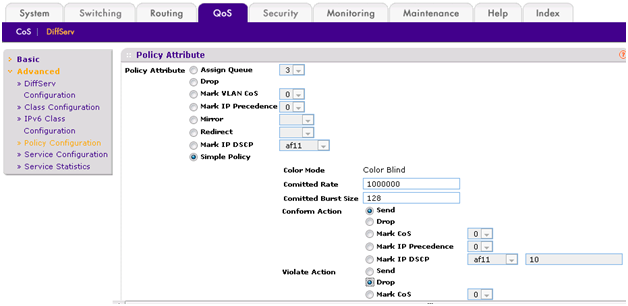
- Configure the following policy attributes:
- Assign Queue. 3.
- Policy Attribute. Simple Policy.
- Color Mode. Color Blind.
- Committed Rate. 1000000 Kbps.
- Committed Burst Size. 128 KB.
- Confirm Action. Send.
- Violate Action. Drop.
- Select QoS> DiffServ> Advanced >Service Configuration.
- On the Service Configuration screen, select the check box next to interfaces g7 and g8.
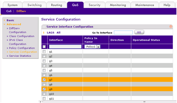
- Click the Apply button.
The policy is attached to interfaces g7 and g8 and the policy is activated.
The new policy directs traffic in the network in the following way:
- All UDP packet flows that have an IP source address of the 192.12.1.0 network, that have a Layer 4 source port of 4567 and a destination port of 4568, that are destined for the 192.12.2.0 network, and that are sent from switch ports 7 and 8 are assigned to hardware queue 3.
- Traffic from streaming applications uses UDP port 4567 as the source port and UDP port 4568 as the destination port. This real-time traffic is time sensitive, so it is assigned to a high-priority hardware queue. By default, data traffic uses hardware queue 0, which is designated as a best-effort queue.
- The confirmed action on this flow is to send the packets with a committed rate of 1,000,000Kbps and a burst size of 128 KB. Packets that violate the committed rate and burst size are dropped.