

This document describes how to configure NETGEAR ProSAFE VPN Firewalls in a hub and spoke VPN system, as might be used between a headquarters and branch offices.
VPN firewalls DGFV338, FVS336G, FVS338 and FVX538 are used with the firmware shown in the table below. The process applies generally to all NETGEAR VPN firewalls.
An example network layout is as follows:
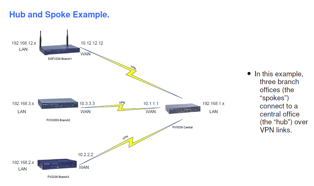
Each branch office (spoke) makes a VPN connection to the central office (the hub). Over these VPN connections, the LAN computers at each branch office can reach the LAN computers at the central office and through these, can reach the LAN computers at the other branch offices.
In this example, each LAN uses a private IP address in which the first two octets are the same for all four LANs (192.168.x.x). The third octet is different for each LAN.
These are the WAN and the LAN addresses:

In each spoke firewall, you configure a VPN tunnel to the hub with a destination subnet mask of 255.255.0.0, indicating that all 192.168.x.x addresses can be reached through the tunnel to the hub. At the hub, we will configure separate tunnels to each spoke with destination subnet masks of 255.255.255.0. The tunnels from the hub will have a source subnet mask of 255.255.0.0, indicating that hosts from any 192.168.x.x address can access the tunnel to the spoke.
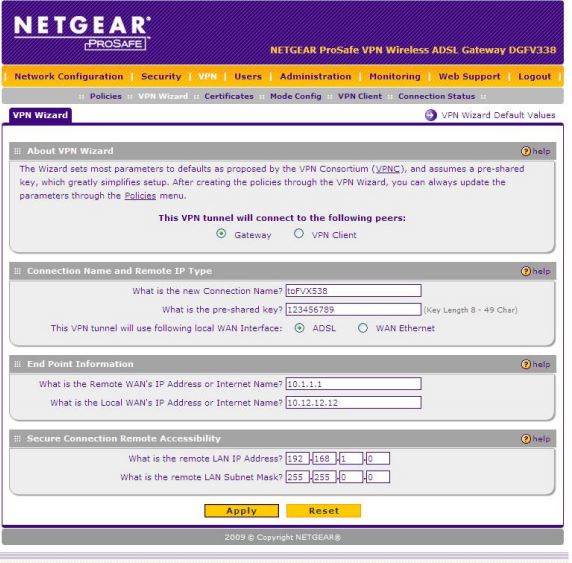
Configuring Branch 1: The DGFV338 Spoke Firewall.
To configure the tunnel to the hub from the DGFV338, use the VPN Wizard to create the VPN policy with settings as below to match our example.
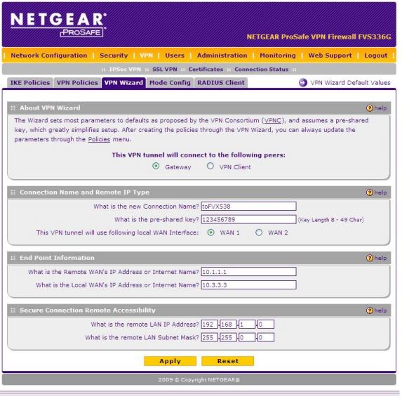
Configuring Branch 2: The FVS336G Spoke Firewall.
To configure the tunnel to the hub from the FVS336G, again use the VPN Wizard to create the VPN policy with settings as below to match our example.
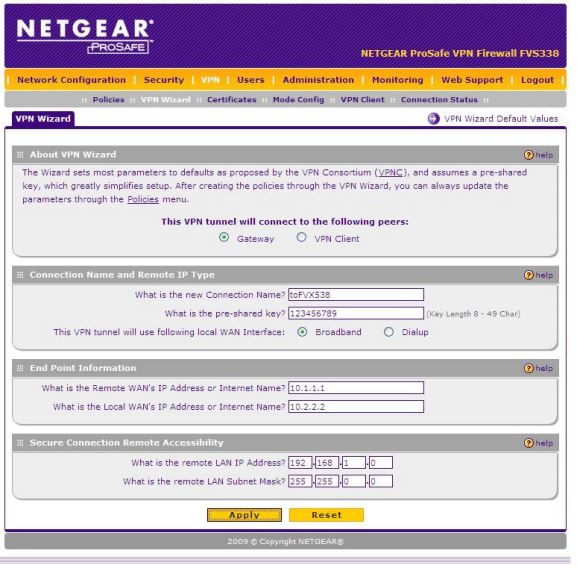
Configuring Branch 3: The FVS338 Spoke Firewall.
To configure the tunnel to the hub from the FVS338, again use the VPN Wizard to create the VPN policy with settings as below to match our example.
Configuring the Central Office: The FVX538 Hub Firewall.
At the hub firewall, you will need to configure a tunnel to each of the three spoke firewalls.
Use the VPN Wizard to create each VPN policy. Below is an example of creating the tunnel to Branch 2 using the VPN Wizard. You repeat for Branch 1 and 3. The differences are the Remote WAN IP, and the remote LAN subnet. In this example, it is just the 3rd octet that changes, eg 3, 2, 12.
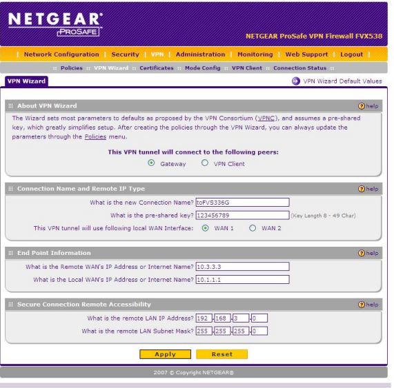
Once you run the VPN Wizard, you will be brought to the VPN Policies screen. Check the policy, especially that the WAN IP on the opposite end is correct. Otherwise, the Wizard should have performed the setup, and you should not have to make edits here. Preshared key can be different per tunnel, but must be the same at both ends. Subnet mask stays at /24 or 255.255.255.0 in all policies in this example.
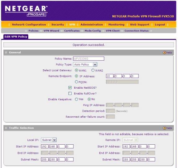
You will now need to repeat this procedure for each of the other two spokes.
Keep alive is optional, and is a preference for the user. It depends on the volume of data activity on the VPN link.
Suggestions are that the Ping IP address be the LAN IP, or a server on the opposite end.
Detection 40 secs.
Count=3.
One keep alive per tunnel is enough.
Testing the Connection.
1. From a PC on the LAN of any branch, you should now be able to successfully ping a PC on the central office’s LAN.
2. From the same branch, you should also now be able to successfully ping a PC on the LAN of any other branch.
Further information:
For VPN Index, click here
The software manual of your respective router would also have a detailed VPN chapter. Example links are FVS318N , UTM25