

This article describes how to configure VLANs with shared access to the Internet on a NETGEAR Easy Smart Managed Switch with a traditional user interface (UI).
For an article with the same topic for a NETGEAR Easy Smart Managed Switch with an Easy Smart UI, see How to configure VLANs with shared access to the Internet on a NETGEAR Easy Smart Managed Switch with an Easy Smart UI?
Note: For this type of configuration, the Internet router that you are using must be VLAN-aware. The devices in each VLAN are not allowed to communicate with devices in other VLANs because inter-VLAN routing is disabled on the router.
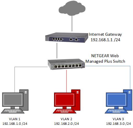
In this example, we configure three VLANs:
- VLAN 1 / network IP address 192.168.1.0 (mask 255.255.255.0)
- VLAN 2 / network IP address 192.168.2.0 (mask 255.255.255.0)
- VLAN 3 / network IP address 192.168.3.0 (mask 255.255.255.0)
We configure the switch ports as follows:
- Switch port 1 connects to port 1 on the router. We call this port the trunk port.
- Switch ports 2 and 3 are members of VLAN 2.
- Switch ports 4 and 5 are members of VLAN 3.
- The remaining switch ports are members of default VLAN 1.
The following diagram presents an overview of the network. (The NETGEAR Web Managed Plus Switch is now called the NETGEAR Easy Smart Managed Switch.)
We recommend that you make sure that the switch is running the latest firmware. For more information, see How do I find the firmware version of my Smart Switch or Easy Smart Managed Switch?
To configure VLANs on a switch and then configure VLANs on a router:
Log in to a NETGEAR Easy Smart Managed Switch with a traditional UI:
- Connect your computer to the same network as the switch.
You can use a WiFi or wired network connection, or connect directly to a switch that is off-network using an Ethernet cable. - Launch a web browser.
- In the address field of your web browser, enter the IP address of the switch.
For more information, see How do I access the device UI of my NETGEAR Easy Smart Managed Switch?
The login page displays. - Enter the switch password.
The default password is password. The password is case-sensitive.
The Switch Information page displays.
Create VLAN 2 and VLAN 3 on the switch:
- Select VLAN > 802.1Q > Advanced > VLAN Configuration.
- Select the Advanced 802.1Q VLAN Enable radio button.
Note: A pop-up window opens, informing you that the current VLAN settings will be lost. - Click the OK button.
- Click the Apply button.
Your settings are saved. - In the VLAN ID field, type 2, and click the Add button.
Your settings are saved.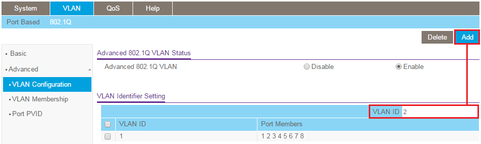
- In the VLAN ID field, type 3, and click the Add button.
Your settings are saved.
Add ports to the VLANs on the switch:
- Select VLAN > 802.1Q > Advanced > VLAN Membership.
- From the VLAN ID menu, select 2.
- Click port 1 until a T displays.
Port 1 connects to the router and must be marked as tagged (T) in VLAN 2. - Click ports 2 and 3 until a U displays.
Ports 2 and 3 connect to client devices and must be marked as untagged (U) in VLAN 2. - Click the Apply button.
Your settings are saved.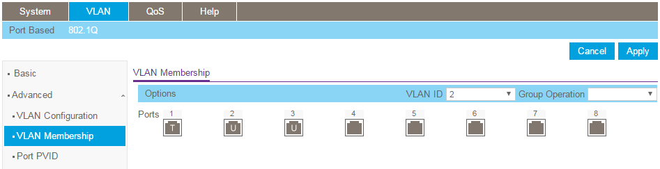
- From the VLAN ID menu, select 3.
- Click port 1 until a T displays.
Port 1 connects to the router and must be marked as tagged (T) in VLAN 3. - Click ports 4 and 5 until a U displays.
Ports 4 and 5 connect to client devices and must be marked as untagged (U) in VLAN 3. - Click the Apply button.
Your settings are saved.
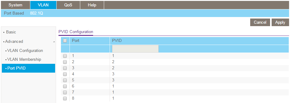
Configure the port PVID settings for untagged ports on the switch:
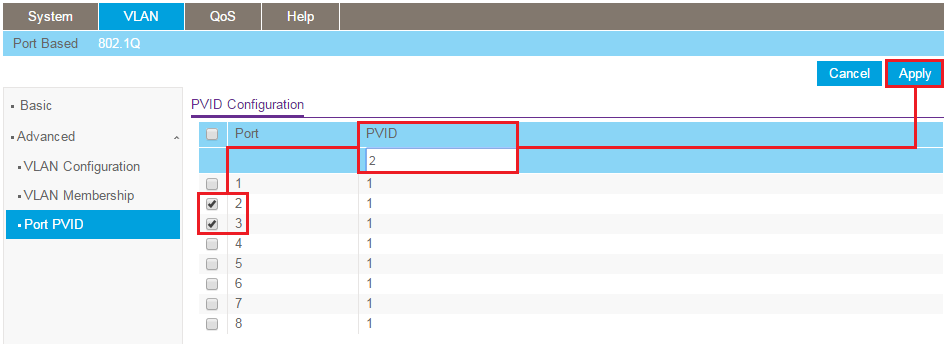
- Go to VLAN > 802.1Q > Advanced > Port PVID.
For each port marked as untagged in the previous procedure, set the PVID of that port to the VLAN ID of the VLAN it was assigned to. - Select the check boxes for ports 2 and 3.
- In the PVID field, enter 2.
- Click the Apply button.
Your settings are saved.
- Select the check boxes for ports 4 and 5.
- In the PVID field, enter 3.
- Click the Apply button.
Your settings are saved.
When you are done, the PVID configuration displays as shown in the following figure.
The following example uses a NETGEAR PR60X Pro Router. The method to configure your router might not be the same but the same principles might apply. Refer to the documentation for your router if you are not sure how to complete the configuration of your router.
Log in to the PR60X Pro Router:
- Launch a web browser from a computer or mobile device that is connected to the router network.
- In the address field of your browser, enter https://www.routerlogin.net.
The login page displays - Your browser might display a security warning. For more information, see What do I do if I my browser displays a security message?
- Type one of the following passwords:
- Type the router user name and password. The user name is admin.
The password is the one that you specified when you set up the router. The user name and password are case-sensitive. - If you are managing the router through the Insight Cloud Portal or Insight app,
type the Insight network password for the Insight network location to which the router is added.
The Dashboard displays.
On the PR60X Pro Router, create VLAN 2:
- Select LAN > VLAN Settings.
The VLAN Settings page displays. - Click the Add VLAN Profile button.
The Add New VLAN Profile pop-up window displays. - In the VLAN ID field, type 2.
- Keep the Inter VLAN Routing toggle gray and position to the left.
- Traffic between this VLAN and other VLANs on the router is restricted.
- In the IP Address field, type 192.168.2.1.
- In the Subnet Mask field, type 255.255.255.0.
- In the DHCP Server section, click the Status toggle so that it is blue and positioned to the right.
The DHCP server is enabled and assigns an IP address to the devices on this VLAN. - In the Start Address field, type 192.168.2.100 as the start address for the DHCP server.
- In the End Address field, type 192.168.2.254 as the end address for the DHCP server.
- Select the Use these DNS Servers button.
- In the DNS1 field, type 192.168.2.1.
- Click the Apply button.
Your settings are saved. The new VLAN profile is added to the VLAN Settings page. - Remain on the same page but scroll down to the Assign VLANs to Wired Ports section at the bottom of the page.
- For VLAN 2, select Tagged in the LAN 1 column.
The LAN 1 port is already an untagged member of VLAN 1, so for VLAN 2, the LAN 1 port must be a tagged member. - Click the Apply button.
Your settings are saved.
On the PR60X Pro Router, create VLAN 3:
- Select LAN > VLAN Settings.
The VLAN Settings page displays. - Click the Add VLAN Profile button.
The Add New VLAN Profile pop-up window displays. - In the VLAN ID field, type 3.
- Keep the Inter VLAN Routing toggle gray and position to the left.
- Traffic between this VLAN and other VLANs on the router is restricted.
- In the IP Address field, type 192.168.3.1.
- In the Subnet Mask field, type 255.255.255.0.
- In the DHCP Server section, click the Status toggle so that it is blue and positioned to the right.
The DHCP server is enabled and assigns an IP address to the devices on this VLAN. - In the Start Address field, type 192.168.3.100 as the start address for the DHCP server.
- In the End Address field, type 192.168.3.254 as the end address for the DHCP server.
- Select the Use these DNS Servers button.
- In the DNS1 field, type 192.168.3.1.
- Click the Apply button.
Your settings are saved. The new VLAN profile is added to the VLAN Settings page. - Remain on the same page but scroll down to the Assign VLANs to Wired Ports section at the bottom of the page.
- For VLAN 3, select Tagged in the LAN 1 column.
The LAN 1 port is already an untagged member of VLAN 1, so for VLAN 3, the LAN 1 port must be a tagged member. - Click the Apply button.
Your settings are saved.
Test your VLAN configuration:
- Connect a computer to a port on the switch in VLAN 2.
- Connect a computer to a port on the switch in VLAN 3.
- Disable the WiFi connection on both computers.
- Verify that the computers cannot access each other because inter-VLAN routing is disabled.
- Verify that each computer can access the Internet.