

This article describes how to configure routing VLANs with shared access to the Internet on a NETGEAR fully managed switch.
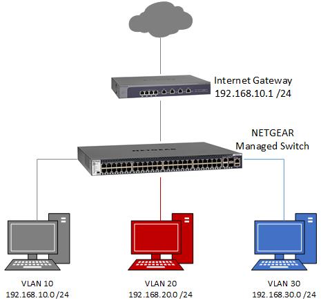
In this example, there are three VLANs configured on the switch:
- VLAN 10: network 192.168.10.0 (mask 255.255.255.0), ports 1 - 10
- VLAN 20: network 192.168.20.0 (mask 255.255.255.0), ports 11 - 20
- VLAN 30: network 192.168.30.0 (mask 255.255.255.0), ports 21 - 28
The devices in each VLAN are allowed to communicate with devices in other VLANs because routing is enabled on the switch. This inter-VLAN communication can be restricted using optional access control lists or ACLs (described later in this article).
The devices in each VLAN access the Internet through an Internet gateway or router that is connected in VLAN 10. In this example, the router is not configured to be VLAN aware but does support static routes. The fully managed switch has routing enabled to route traffic between VLANs, from the devices in VLANs 10, 20, and 30 to the router, and back.
The following diagram presents an overview of the network.
To configure routing VLANs with shared Internet access on a NETGEAR fully managed switch and a NETGEAR PR60X Pro Router:
Log in to the fully managed switch:
- Launch a web browser and enter the IP address of the switch in the address field of your web browser.
The login page displays. - Click the Main UI Login button.
The main UI login page displays in a new tab. - Enter admin as the user name and enter one of the following passwords:
- Enter your local device password.
The first time that you log in, no password is required. However, you then must specify
a local device password to use each subsequent time that you log in. - If you are managing the switch through the Engage controller, enter the site password
for the Engage site to which the switch is onboarded. - If, in addition to the main UI, you are also managing the switch through the Insight Cloud Portal
or Insight app, enter the Insight network password for the Insight network to which the switch is added.
- Click the Login button.
The System Information page displays.
Create the routing VLANs on the fully managed switch:
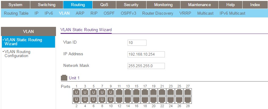
- Select Routing > VLAN > VLAN Static Routing Wizard.
- Create VLAN 10 by configuring the following fields:
- VLAN ID: Type 10.
- IP Address: Type 192.168.10.254.
- Network Mask: Type 255.255.255.0.
- Click ports 1 through 10 until a U displays.
Ports that connect to end devices such as computers should be marked as untagged (U). Ports that carry traffic for multiple VLANs on other VLAN-aware devices should be marked as tagged (T).
- Click the Apply button.
Your settings are saved.
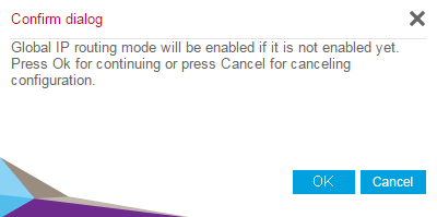
Note that this action removes the selected ports from the default VLAN (VLAN 1). If you are managing the switch through a port in VLAN 1, be careful not to reconfigure the port through which you are managing the switch, otherwise you are locked out. - When prompted with the Global IP routing mode window, click the OK button.
- Create VLAN 20 by configuring the following fields:
- VLAN ID: Type 20.
- IP Address: Type 192.168.20.254.
- Network Mask: Type 255.255.255.0.
- Click ports 11 through 20 until a U displays.
- Click the Apply button.
Your settings are saved. - Create VLAN 30 by configuring the following fields:
- VLAN ID: Type 30.
- IP Address: Type 192.168.30.254.
- Network Mask: Type 255.255.255.0.
- Click ports 21 through 28 until a U displays.
- Click the Apply button.
Your settings are saved.
Configure the DHCP server on the fully managed switch (optional):
If you require the switch to function as a DHCP server for the VLANs, follow the steps in this section. If not, proceed to the Add a default route section.
- Select System > Services > DHCP Server > DHCP Server Configuration.
- Select the Admin Mode Enable radio button.
- Click the Apply button.
Your settings are saved. - Select System > Services > DHCP Server > DHCP Pool Configuration.
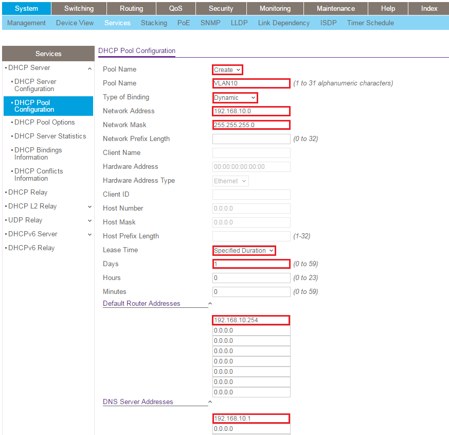
- Create a DHCP pool for VLAN 10 by configuring the following settings:
- Pool Name menu: Select Create.
- Pool Name field: Type VLAN10.
- Type of binding: Select Dynamic.
Note: When you select Dynamic, the association between a DHCP pool and a VLAN is based on the IP address and network mask that are assigned to the VLAN. To associate a DHCP pool to a VLAN, ensure that the network address of the pool matches the network address of the VLAN. For example, VLAN 10 in this example is assigned the IP address 192.168.10.254 and network mask 255.255.255.0. This means a network address of 192.168.10.0. When you create the DHCP pool for VLAN 10, ensure that the network address is 192.168.10.0 with network mask 255.255.255.0. The switch automatically assigns the DHCP pool to the corresponding VLAN (VLAN 10 in this example). - Network Address: Type 192.168.10.0.
- Network Mask: Type 255.255.255.0.
- Lease Time: Select Specified Duration.
- Days: Type 1.
- Default Router Addresses: Type 192.168.10.254.
The default router address used for a pool is the IP address of the corresponding VLAN interface. For VLAN 10, it is 192.168.10.254. - DNS Server Addresses: Type 192.168.10.1.
- Click the Add button.
Your settings are saved. - Create a DHCP pool for VLAN 20 by configuring the following settings:
- Pool Name menu: Select Create.
- Pool Name field: Type VLAN20.
- Type of binding: Select Dynamic.
- Network Address: Type 192.168.20.0.
- Network Mask: Type 255.255.255.0.
- Lease Time: Select Specified Duration.
- Days: Type 1.
- Default Router Addresses: Type 192.168.20.254.
- DNS Server Addresses: Type 192.168.20.1.
- Click the Add button.
Your settings are saved. - Create a DHCP pool for VLAN 30 by configuring the following settings:
- Pool Name menu: Select Create.
- Pool Name field: Type VLAN30.
- Type of binding: Select Dynamic.
- Network Address: Type 192.168.30.0.
- Network Mask: Type 255.255.255.0.
- Lease Time: Select Specified Duration.
- Days: Type 1.
- Default Router Addresses: Type 192.168.30.254.
- DNS Server Addresses: Type 192.168.30.1.
- Click the Add button.
Your settings are saved. - Select System > Services > DHCP Server > DHCP Server Configuration.
- In the Excluded Address table, in the IP Range From field, type 192.168.10.1.
This IP address must not be offered by the DHCP server. - Click the Add button.
Your settings are saved. - Repeat steps 12 and 13 for the following three IP addresses, corresponding to the default router addresses for the VLANs that you set up:
- 192.168.10.254
- 192.168.20.254
- 192.168.30.254
Add a default route on the fully managed switch:
Add a default route on the fully managed switch so that traffic that is not destined for the local VLANs is routed to the Internet gateway or router.
- Select Routing > Routing Table > Basic > Route Configuration.
- From the Route Type menu, select Default.
- In the Next Hop Address field, type 192.168.10.1, which is the IP address of the router in this example.

- Click the Add button.
Your settings are saved.
Log in to the PR60X Pro Router:
This example uses a NETGEAR PR60X Pro Router, but you could use any other type of router or Internet gateway. The configuration of other routers or Internet gateways will vary but the principles are the same. For more information, see the documentation for your product.
- Launch a web browser from a computer or mobile device that is connected to the router network.
- In the address field of your browser, enter https://www.routerlogin.net.
The login page displays - Your browser might display a security warning. For more information, see What do I do if I my browser displays a security message?
- Type one of the following passwords:
- Type the router user name and password. The user name is admin.
The password is the one that you specified when you set up the router. The user name and password are case-sensitive. - If you are managing the router through the Insight Cloud Portal or Insight app,
type the Insight network password for the Insight network location to which the router is added.
The Dashboard displays.
Add static routes on the PR60X Pro Router:
Add static routes to the router to ensure that the router can return traffic to devices in VLANs that are not directly attached to the router (that is, devices that are attached to VLANs 20 and 30 in this example). You do not need to create a static route for VLAN 10 because the router is connected directly to VLAN 10 on the fully managed switch.
- Select LAN > Static Routes.
- Click the Add icon.
- Configure the following settings for VLAN 20:
- Route Name: Type VLAN 20.
- Network: Type 192.168.20.0.
- Subnet Mask: Type 255.255.255.0.
- Gateway: Type 192.168.10.254.
- Metric: Type 2.
- Interface: Select VLAN1.
The VLAN 1 interface is the default LAN interface. We are selecting this interface because, in this example, the router is not configured to be VLAN-aware.
- Click the Apply button.
Your settings are saved. - Configure the following settings for VLAN 30:
- Route Name: Type VLAN 30.
- Network: Type 192.168.30.0.
- Subnet Mask: Type 255.255.255.0.
- Gateway: Type 192.168.10.254.
- Metric: Type 2.
- Interface: Select VLAN1.
- Click the Apply button.
Your settings are saved.
Configure access control lists on the fully managed switch (optional):
As an option, add access control lists (ACLs) to prevent unwanted inter-VLAN communication. For example, we want to allow the devices in VLAN 20 to communicate with the router but prevent communication with other devices in VLANs 10 and 30.
Create IP ACLs on the fully managed switch:
For information about logging in to the fully managed switch, see the first task in this article.
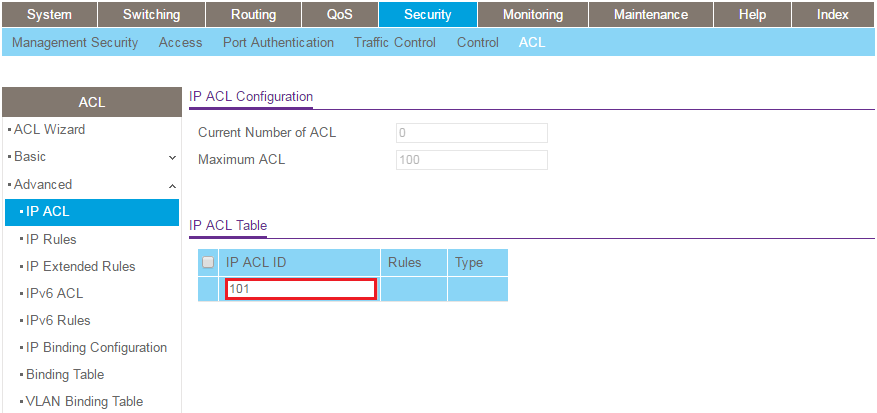
- Select Security > ACL > Advanced > IP ACL.
- In the IP ACL Table, type 101 in the IP ACL ID field.
ACL 101 is used for VLAN 10. - Click the Add button.
Your settings are saved.
- In the IP ACL Table, type 102 in the IP ACL ID field.
ACL 102 is used for VLAN 20. - Click the Add button.
Your settings are saved. - In the IP ACL Table, type 103 in the IP ACL ID field.
ACL 103 is used for VLAN 30. - Click the Add button.
Your settings are saved.
Add rules to ACL 101 (for VLAN 10) on the fully managed switch:
- Select Security > ACL > Advanced > IP Extended Rules.
- From the ACL ID/Name menu, select 101.
- Click the Add button.
Your settings are saved. - Configure the first rule (ignore the fields that are not listed here):
- Sequence Number: Type 10.
- Action: Select the Deny radio button.
- Src: Select the IP address radio button, and type 192.168.10.0 in the first field and 0.0.0.255 in the second field.
- Dst: Select the IP address radio button, and type 192.168.20.0 in the first field and 0.0.0.255 in the second field.
- Click the Apply button.
Your settings are saved. - Click the Add button.
- Configure the second rule (ignore the fields that are not listed here):
- Sequence Number: Type 20.
- Action: Select the Deny radio button.
- Src: Select the IP address radio button, and type 192.168.10.0 in the first field and 0.0.0.255 in the second field.
- Dst: Select the IP address radio button, and type 192.168.30.0 in the first field and 0.0.0.255 in the second field.
- Click the Apply button.
Your settings are saved. - Click the Add button.
- Configure the third rule (ignore the fields that are not listed here):
- Sequence Number: Type 30.
- Action: Select the Permit radio button.
- Match: Select True from the menu.
- Click the Apply button.
Your settings are saved.
Add rules to ACL 102 (for VLAN 20) on the fully managed switch:
- Select Security > ACL > Advanced > IP Extended Rules.
- From the ACL ID/Name menu, select 102.
- Click the Add button.
Your settings are saved. - Configure the first rule (ignore the fields that are not listed here):
- Sequence Number: Type 10.
- Action: Select the Permit radio button.
- Src: Select the IP address radio button, and type 192.168.20.0 in the first field and 0.0.0.255 in the second field.
- Dst: Select the Host radio button, and type 192.168.10.1 in the field.
- Click the Apply button.
Your settings are saved. - Click the Add button.
- Configure the second rule (ignore the fields that are not listed here):
- Sequence Number: Type 20.
- Action: Select the Deny radio button.
- Src: Select the IP address radio button, and type 192.168.20.0 in the first field and 0.0.0.255 in the second field.
- Dst: Select the IP address radio button, and type 192.168.10.0 in the first field and 0.0.0.255 in the second field.
- Click the Apply button.
Your settings are saved. - Click the Add button.
- Configure the third rule (ignore the fields that are not listed here):
- Sequence Number: Type 30.
- Action: Select the Deny radio button.
- Src: Select the IP address radio button, and type 192.168.20.0 in the first field and 0.0.0.255 in the second field.
- Dst: Select the IP address radio button, and type 192.168.30.0 in the first field and 0.0.0.255 in the second field.
- Click the Apply button.
Your settings are saved. - Click the Add button.
- Configure the fourth rule (ignore the fields that are not listed here):
- Sequence Number: Type 40.
- Action: Select the Permit radio button.
- Match: Select True from the menu.
- Click the Apply button.
Your settings are saved.
Add rules to ACL 103 (for VLAN 30) on the fully managed switch:
- Select Security > ACL > Advanced > IP Extended Rules.
- From the ACL ID/Name menu, select 103.
- Click the Add button.
Your settings are saved. - Configure the first rule (ignore the fields that are not listed here):
- Sequence Number: Type 10.
- Action: Select the Permit radio button.
- Src: Select the IP address radio button, and type 192.168.30.0 in the first field and 0.0.0.255 in the second field.
- Dst: Select the Host radio button, and type 192.168.10.1 in the field.
- Click the Apply button.
Your settings are saved. - Click the Add button.
- Configure the second rule (ignore the fields that are not listed here):
- Sequence Number: Type 20.
- Action: Select the Deny radio button.
- Src: Select the IP address radio button, and type 192.168.30.0 in the first field and 0.0.0.255 in the second field.
- Dst: Select the IP address radio button, and type 192.168.10.0 in the first field and 0.0.0.255 in the second field.
- Click the Apply button.
Your settings are saved. - Click the Add button.
- Configure the third rule (ignore the fields that are not listed here):
- Sequence Number: Type 30.
- Action: Select the Deny radio button.
- Src: Select the IP address radio button, and type 192.168.30.0 in the first field and 0.0.0.255 in the second field.
- Dst: Select the IP address radio button, and type 192.168.20.0 in the first field and 0.0.0.255 in the second field.
- Click the Apply button.
Your settings are saved. - Click the Add button.
- Configure the fourth rule (ignore the fields that are not listed here):
- Sequence Number: Type 40.
- Action: Select the Permit radio button.
- Match: Select True from the menu.
- Click the Apply button.
Your settings are saved.
Bind (add) the ACLs to the ports on the fully managed switch:
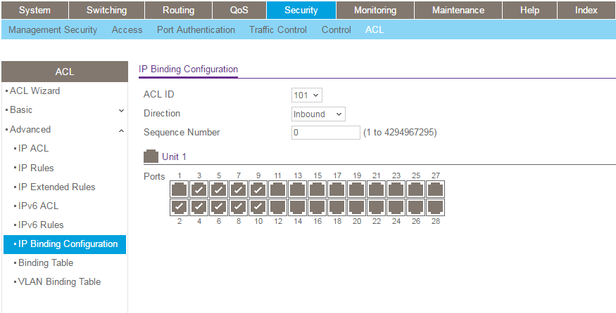
- Select Security > ACL > Advanced > IP Binding Configuration.
- From the ACL ID menu, select 101.
- Click ports 1 through 10 to select them.
These are the ports that you earlier assigned to VLAN 10. Do not select port 1 because that is the port that connects to the router (or Internet gateway).
- Click the Apply button.
Your settings are saved. - From the ACL ID menu, select 102.
- Click ports 11 through 20 to select them.
These are the ports that you earlier assigned to VLAN 20. - Click the Apply button.
Your settings are saved. - From the ACL ID menu, select 103.
- Click ports 21 through 28 to select them.
These are the ports that you earlier assigned to VLAN 30. - Click the Apply button.
Your settings are saved.