Configuration Steps

Create a Redundant Link (LAG) Between the ReadyDATA and Switch
Since virtual machines require permanent access to network storage to stay online, the network connection between the hypervisor (VMware) and the storage is mission critical. Link aggregation is one way to achieve higher redundancy for this connection. For this app note we will be creating port trunks of two for each device (switch, ReadyDATA, and ESXi server). This will provide our virtualization infrastructure with the end-to-end network redundancy to endure a link failure. In this section, we will be creating a LAG between the ReadyDATA and switch.
Order of Configuration
The order in which the LAGs are created is important, as changing the order outlined below might result in a loss of connectivity to the ReadyDATA management UI. In the event that you lose connectivity to the ReadyDATA, you can reset its network configuration by using a special boot sequence found in the link below: https://kb.netgear.com/app/answers/detail/a_id/23044
Switch Side Configuration
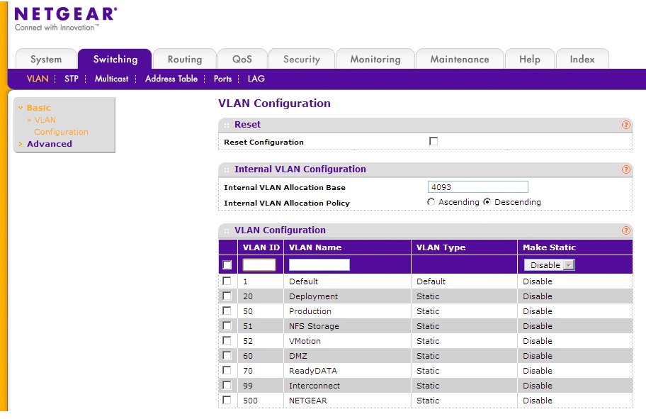
Before we get into LAG configuration, be sure to create a dedicated storage VLAN. In the management interface of the switch, go to Switching -> VLAN and create the VLAN (In our example it is VLAN 51 and we name it NFS Storage).
After creating the storage VLAN, go to Switching -> LAG. You will see the different port channels available on the switch. Select a channel that is unused (in this example it is ch5) and check the box next to it. At the top row, enter in the details such as LAG Name and Admin mode. Make sure the Enable option is selected in Admin Mode. This determines whether the LAG is enabled or not. For this particular port channel we will also set Static Mode as Disable as we will be using LACP rather than just a static LAG.

Now click Apply.

The LAG RD-VMware is now created.
Next, we will add ports to this LAG. Go to Switching -> LAG -> LAG Membership. In the LAG ID field, select the Lag that we just configured. Once you have that selected, click on the Unit 1 button to display the ports on the switch and select the ports you wish to add to the LAG. In our example we add ports 49 and 50 as members of the LAG.
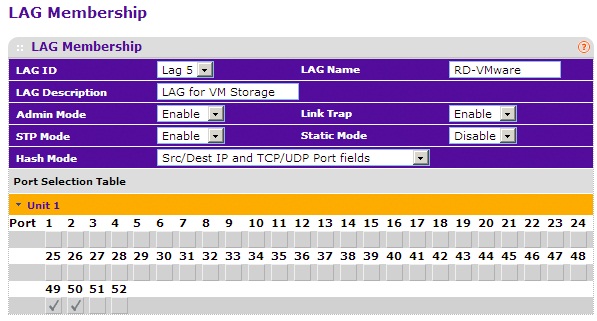
Finally, click Apply.

As you can see above, the LAG RD-VMware has been assigned ports and its LAG State is UP.
The next step will be to add the LAG to our storage VLAN (VLAN 51). Go to Switching -> VLAN.

Here you can see our storage VLAN – NFS Storage VLAN 51. On the menu to the left, go to Advanced-> VLAN Membership. In the VLAN ID drop down menu, select 51. At the bottom, find the checkbox for LAG 5 and left click on it until it shows “T” (which stands for tagged). Click APPLY.
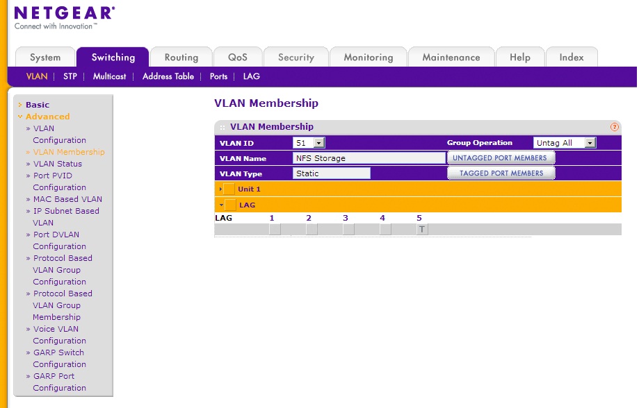
The LAG on the switch side is now properly configured.
ReadyDATA Side Configuration
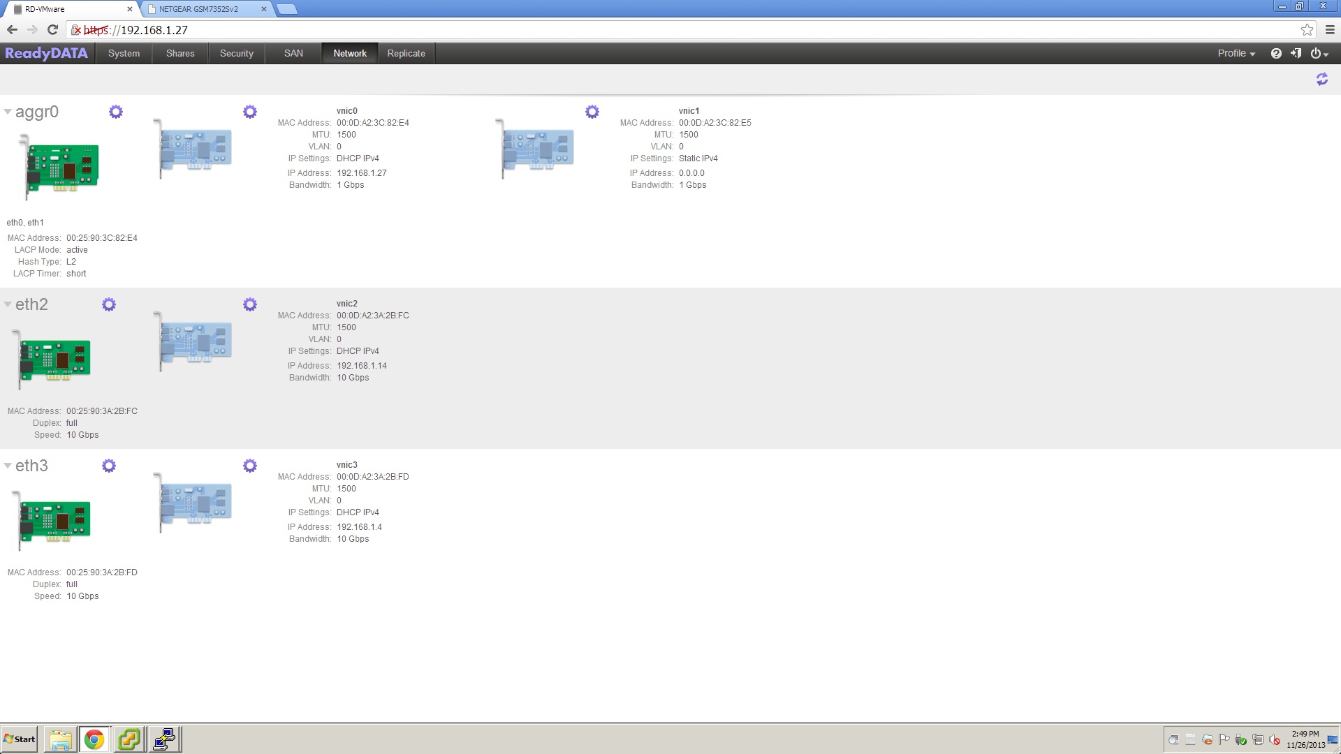
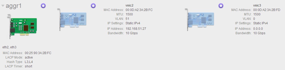
We are now ready to configure a LAG on the ReadyDATA side of things. Login to the GUI and go to Network. What we are going to do here is to configure a vnic for the storage VLAN and then bond that NIC and another NIC together. For this example we will bond the two 10 Gigabit NICs (eth2 and eth3) on the ReadyDATA. Note that we already have eth0 and eth1 in a LAG (aggr0) on the default VLAN for management purposes.
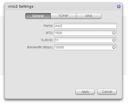
First, left click on the gear icon for vnic2. This will bring up a popup window. Change the VLAN ID to 51.
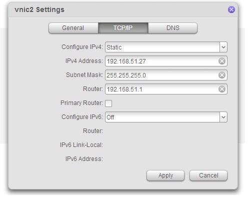
Next, click on the TCP/IP tab. We will now give vnic 2 a static IP address so in the Configure IPv4 drop down menu select Static. Now enter the IP address for the vnic (in our example it is 192.168.51.27). Finally, click Apply.
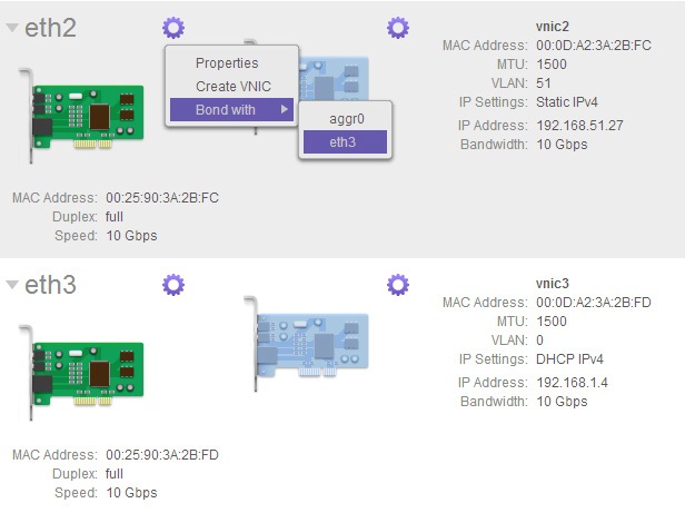
Now, left click on the gear icon for eth2. This will bring up a drop down menu. Select the Bond with option and then eth3 in the next menu level down.
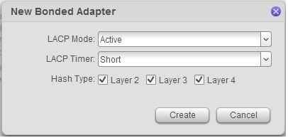
Once you click on eth3 you will see a new popup window to help configure your LACP settings. Set the LACP Mode as Active and LACP Timer as Short. For Hash type, in general to achieve even traffic distribution between physical links within the LAG, it’s best to have more variables or layers to enter into the hashing algorithm. In our example we will check the Layer 2, Layer 3 and Layer 4 boxes to correspond to the hashing method we chose on the switch. Finally, click Create.
We’ve now successfully created a port trunk with eth2 and eth3 named aggr1 and configured a LAG between the ReadyDATA and switch.
Create a Redundant Link (LAG) Between the Switch and ESXi Host
Next we’ll create a LAG between the ESXi host and our switch. We will start with the configuration on the switch.
Switch Side Configuration
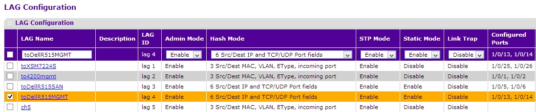
Login to the NETGEAR managed switch and go to Switching -> LAG. Select a channel that is unused and check the box next to it. At the top row, enter in the details such as LAG Name and Admin mode. Make sure the Enable option is selected in Admin Mode. This determines whether the LAG is enabled or not. For this particular port channel we will also set Static Mode as Enable as a static LAG is the recommended setting by VMware. Now click Apply.
Note: With the VMware vSphere Web Client it is now possible to create a LAG with LACP enabled. In such cases the setting here would be to set Static Mode to Disable.
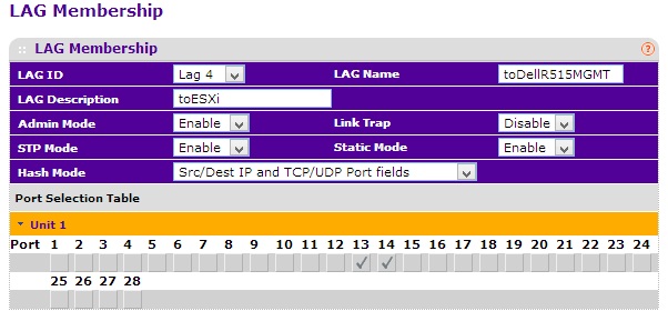
Next, we will add ports to this LAG. Go to Switching -> LAG -> LAG Membership. In the LAG ID field, select the Lag that we just configured. Once you have that selected, click on the Unit 1 button to display the ports on the switch and select the ports you wish to add to the LAG. In our example we add ports 13 and 14 as members of the LAG.
Finally, click Apply.
The LAG on the switch is now properly configured.

VMware Side Configuration
Now we will create a LAG using two previously unused physical adapters on the ESXi host. For this purpose we will create a dedicated vSwitch from the two unused physical adapters for storage traffic with a VLAN ID of 51.
First, login to the ESXi host with the vSphere client and go to the Networking Adapters option on the Configuration tab. On our server vmnic3 and vmnic2 are currently not allocated to any vSwitch. We will use those two in our new vSwitch.
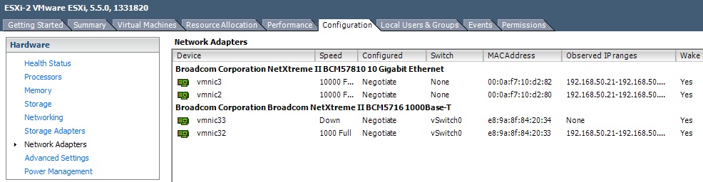
Now that we’ve identified the physical adapters to use, go to Networking on the Configuration tab. Here, you will see the existing vSwitch0 used for management. Now click on the Add Networking… link.

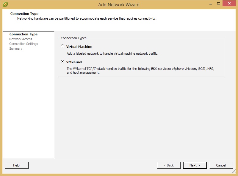
You will be taken to an Add Network Wizard. Select VMkernel and click Next.
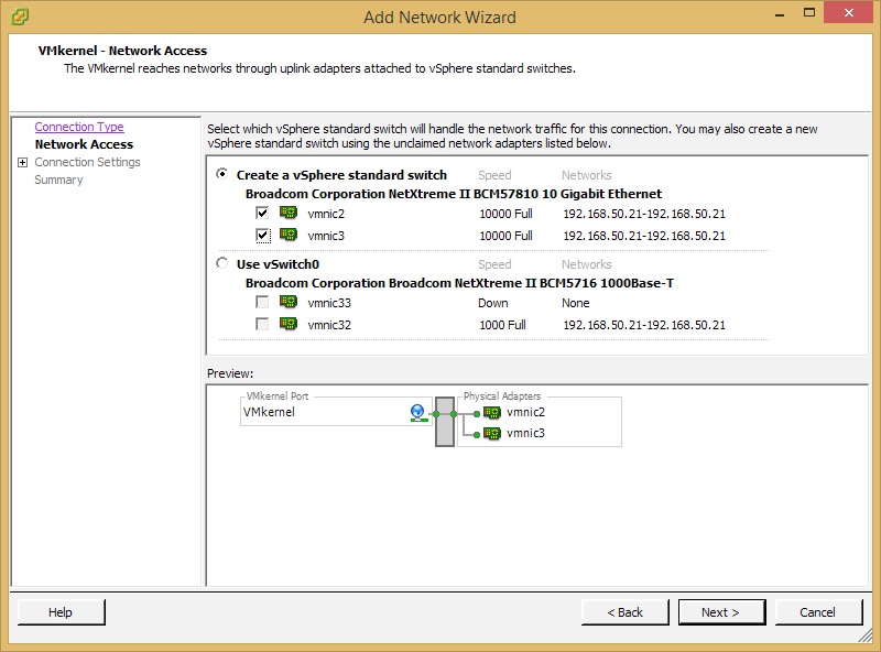
In this step, select the Create a vSphere standard switch option and check the boxes for vmnic2 and vmnic3. Click Next.
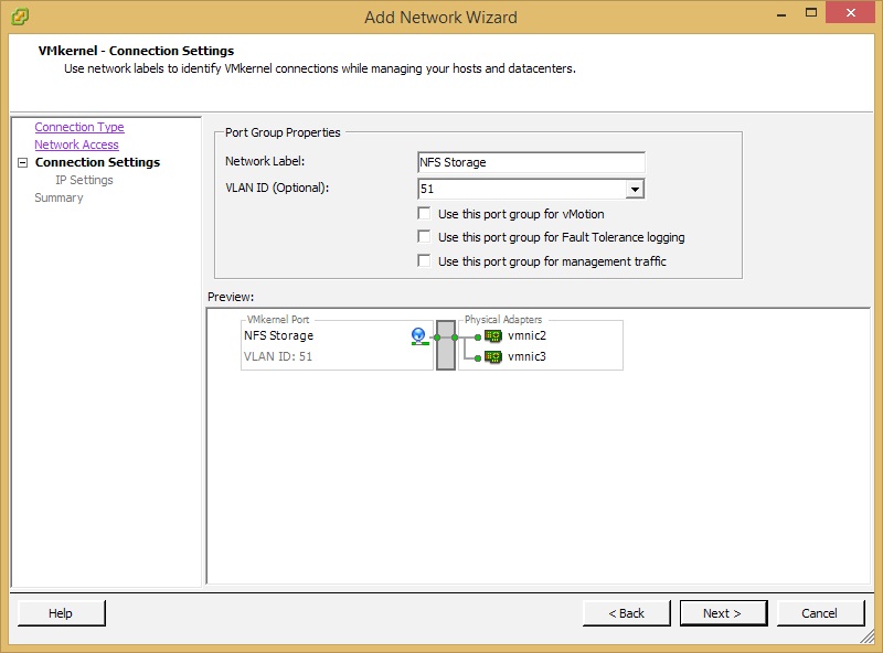
In this step, give the network a label. In this example we will name this network NFS Storage and give it a VLAN ID of 51. Click Next
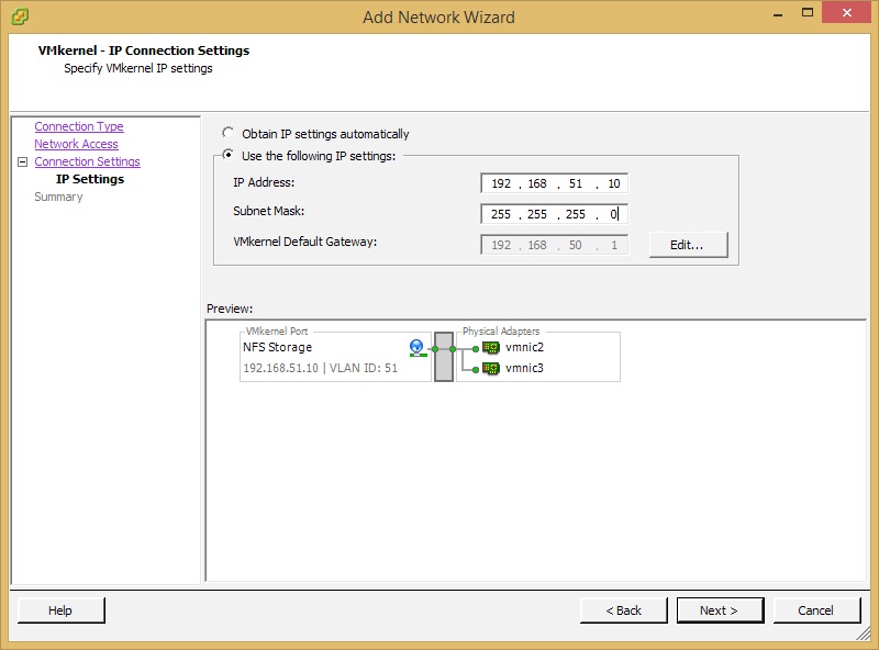
In the IP Settings step, we will give the VMkernel port a static IP on the port range of VLAN 51 (192.168.51.x). We will give it an IP address of 192.168.51.10. Obviously your settings may vary. Click Next.
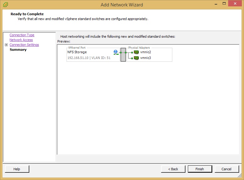
Review the settings and click Finish.
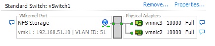
Our new vSwitch1 for storage traffic has now been created. Next, we will configure the two physical ports to run as a LAG. Click Properties….
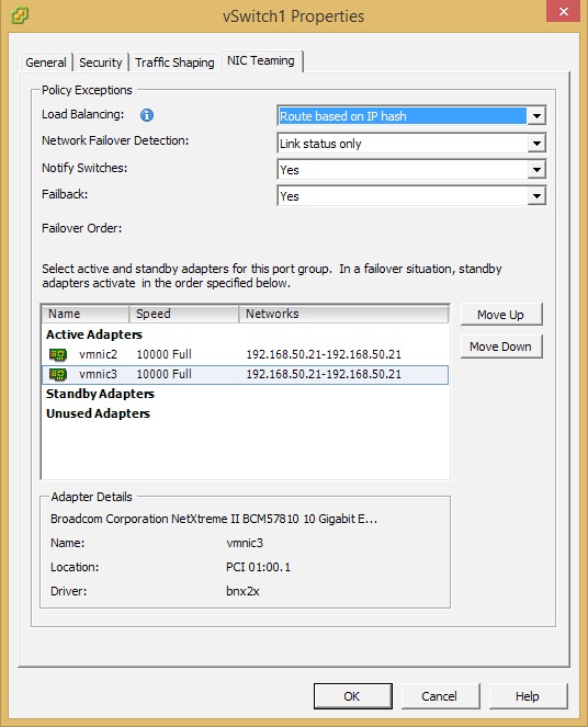
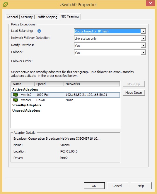
On the vSwitch1 Properties page, find the NIC Teaming tab. To enable link aggregation we must change the Load Balancing setting to Route based on IP hash. Make sure both vmnic2 and vmnic3 are Active A Adapters. Click Ok.
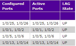
Log back into the switch and go to the Switching -> LAG page and make sure the LAG state is UP.
Create a Volume on the ReadyDATA
Once we have the network side of things taken care of the next step will be to create an NFS data set on the ReadyDATA. The first step to doing this is to (if you haven’t already) create a volume on the ReadyDATA.
Note: In order to preserve your settings, you must create at least one volume on the ReadyDATA.
We highly recommend RAID10 in virtualization deployments as this type of workload is random I/O intensive. It is also recommended to have fewer large volumes, rather than many small volumes. The reason for this is that sharing I/O across volumes is not possible.
In this example we are going to configure one large volume in RAID10. SAS drives are strongly recommended for virtualization, while hybrid disk configurations (SSD + SATA) can be used when performance requirements are lower. RAID10 should always be used for virtualization deployments.
To create a volume:
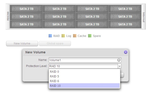
Login to the ReadyDATA GUI and go to System -> Storage. You will see a graphical representation of the ReadyDATA system and populated drives at the middle-top of this page.
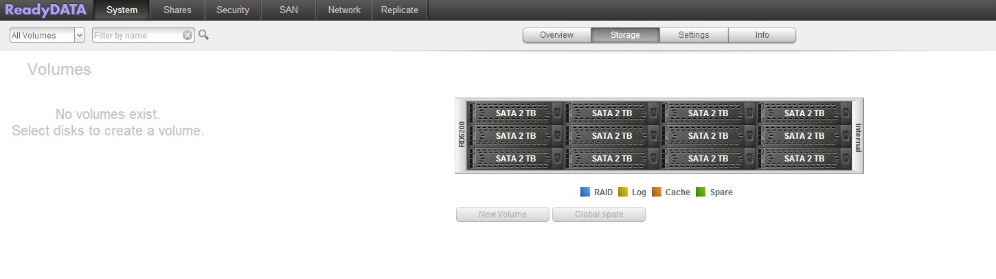
Click on the drives you wish to create the new volume with and click on the New Volume button.
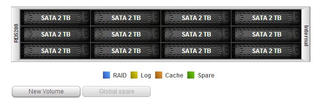
Name your new volume and select the RAID level. The available RAID levels will automatically adjust according to the number of drives you have selected for this new volume. In this example we’ve selected 12 drives and will create a volume with a RAID level of 10 (or 1+0).
Click Create.
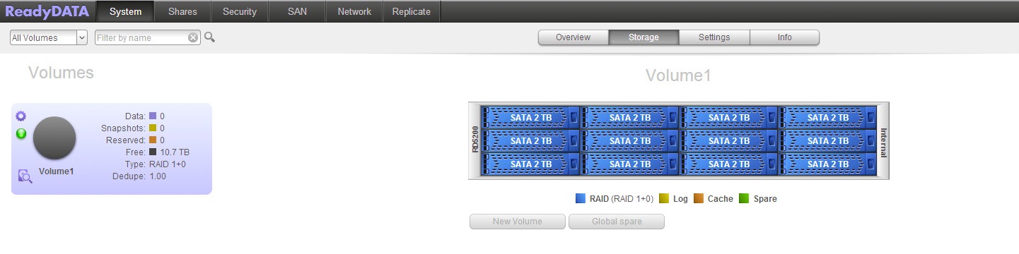
Within a few seconds, our new RAID10 volume is ready to use.
Create an NFS Data Set on the ReadyDATA
After you have created at least one volume on the ReadyDATA, you can create data sets. These are logical storage containers that can be purposed as NAS shares or SAN LUNs. For this app note we will create an NFS data set to be used as the VMware datastore. We recommend using NFS over iSCSI for VMware due to ease of ongoing management and deployment flexibility.
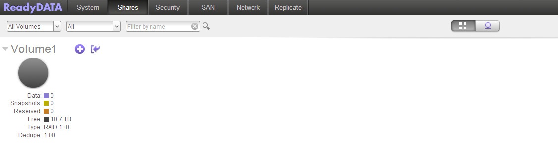
First, go to the Shares page and click on the “+” sign on your volume.
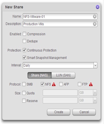
You will now see a New Share window. Enter in the Name, Description, and Protection settings for this data set. For this example we will name our data set NFS-VMware-01. Now check the NFS box and click Create.
Note: If you have not enabled the NFS service on the ReadyDATA you will see a warning icon next to the NFS checkbox as shown in the screenshot below. We will enable the service in the next step.
As a reminder, ReadyDATA features Continuous Protection via unlimited snapshots that should be utilized as an essential added layer of protection for your data. These are block level snapshots that will track changes to your data continuously. If you happen to accidentally delete a file or multiple files or folders, this feature can help you recover your data within a matter of seconds.
You will see the following message.
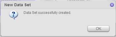
We have now successfully created a NFS data set. 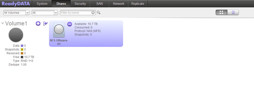
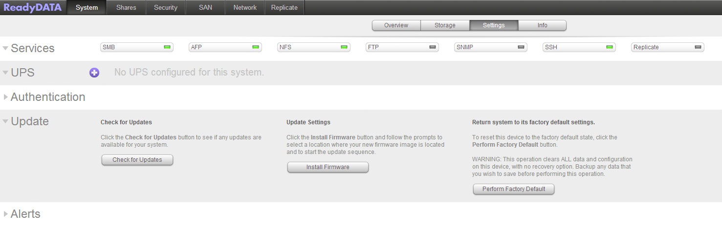
If the NFS service has not already been enabled on your ReadyDATA, go to System -> Settings and in the Services section click on the NFS button so that the status is green.
Now, let’s go back to the Shares page.
Upon creation, no hosts will be allowed to access this new data set. We will now go in and configure the proper access rights. Right click on the NFS-VMware-01 icon and select Properties.
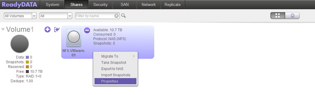
You’ll now see the properties section for the NFS-VMware-01 data set on the right hand side.
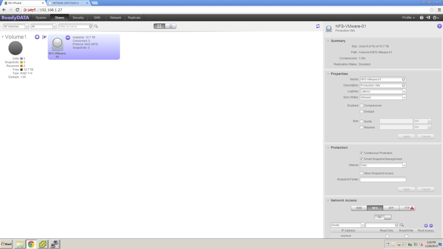
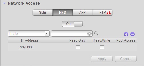
Scroll down to the Network Access section. Select the NFS tab to configure NFS related settings. Once on the NFS tab, we will now configure permissions so that access from our ESXi host (192.168.51.156) is allowed. Click on the “+” button.
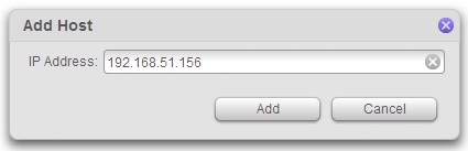
You will see a new Add Host window. Enter in the IP address of your ESXi host and click Add.
Once the host has been added, make sure the Read/Write checkbox is checked for that host. Click Apply.
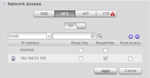
And we’re done with the ReadyDATA end of the configuration. We will now move on to the ESXi side.
One other thing to take note is that under properties in the Summary section, remember to write down the Path for this NFS data set. The Path will be used in the next section.
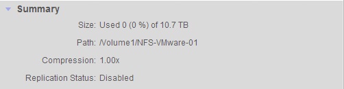
Connecting VMware ESXi Host to NFS Data Set on ReadyDATA
In this section we will connect the ESXi host with the NFS data set we just created.
The first step is to login to the ESXi host with the vSphere client. Once logged in, go to the Storage section on the Configuration tab and click on the Add Storage… button.
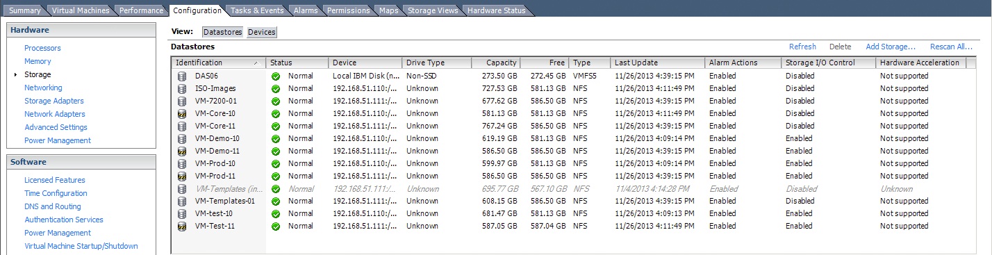
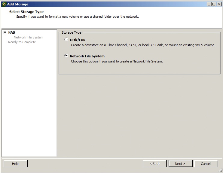
From there, you will be taken to an Add Storage wizard. Because we are using NFS, select the Network File System option and click Next.
Remember the Path for the NFS-VMware-01 data set we wrote down in the previous section? Here is where the wizard will ask for that path.
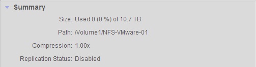
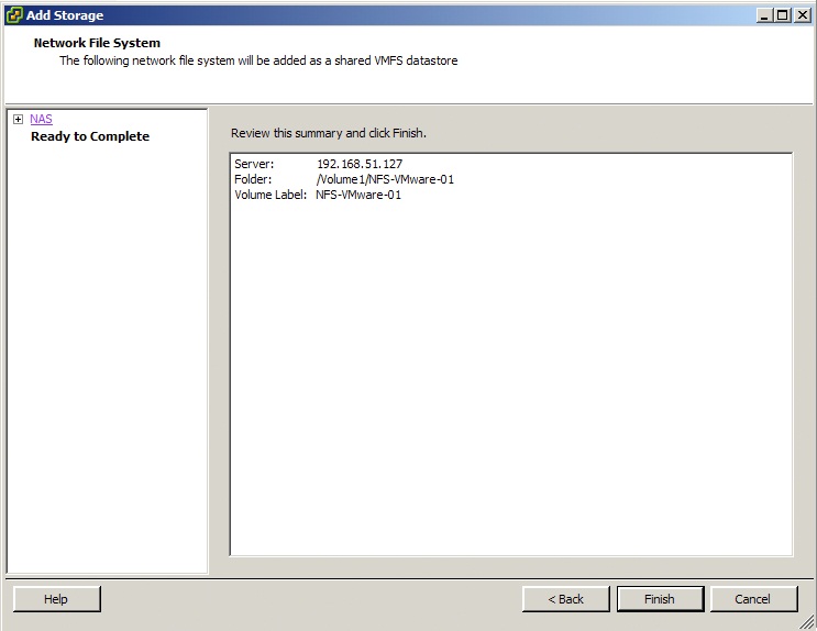
In this step, enter the IP address of the ReadyDATA in the Server field and the Path (in our example it is /Volume1/ NFS-VMware-01, yours should be similar) into the Folder field. Also be sure to give your Datastore a name. Then click Next.

Review and click Finish.
Back in vSphere, you will see the new Datastore being displayed and ready to use.
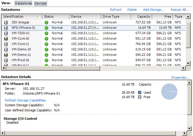
And that’s it! The NFS data set on the ReadyDATA is now being used by VMware ESXi host as a Datastore.
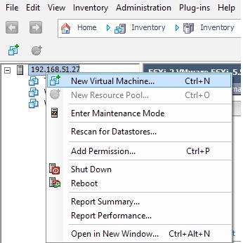
Next, we will create and power on a virtual machine that is stored on the datastore we just created. In vSphere, right click on your host and select New Virtual Machine.
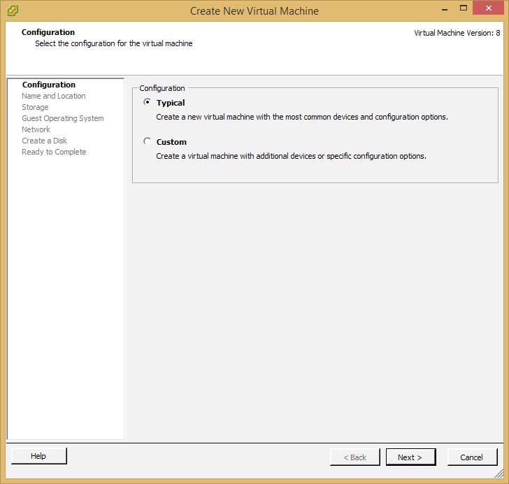
You’ll be taken to a Create New Virtual Machine wizard. For our example we will create a virtual machine that will be used to host a Windows 7 64bit OS. Select Typical and click Next.
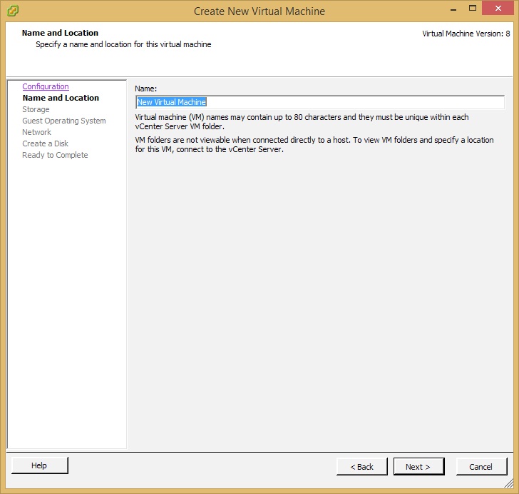
Next, give your virtual machine a name and click Next.
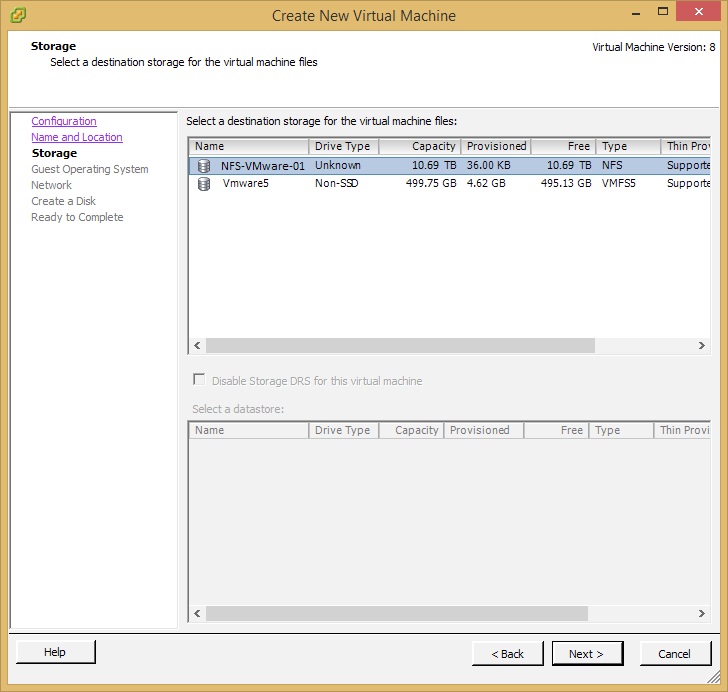
Now select which datastore to store the virtual machine files. We will use the NFS datastore NFS-VMware-01 we created earlier in the application note. Select it and click Next.
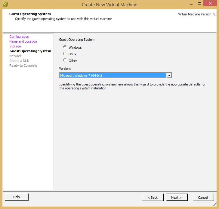
Since we are creating a virtual machine for a Windows 7 64bit OS, select Windows, in the Version drop down menu choose Microsoft Windows 7 (64bit) and click Next.
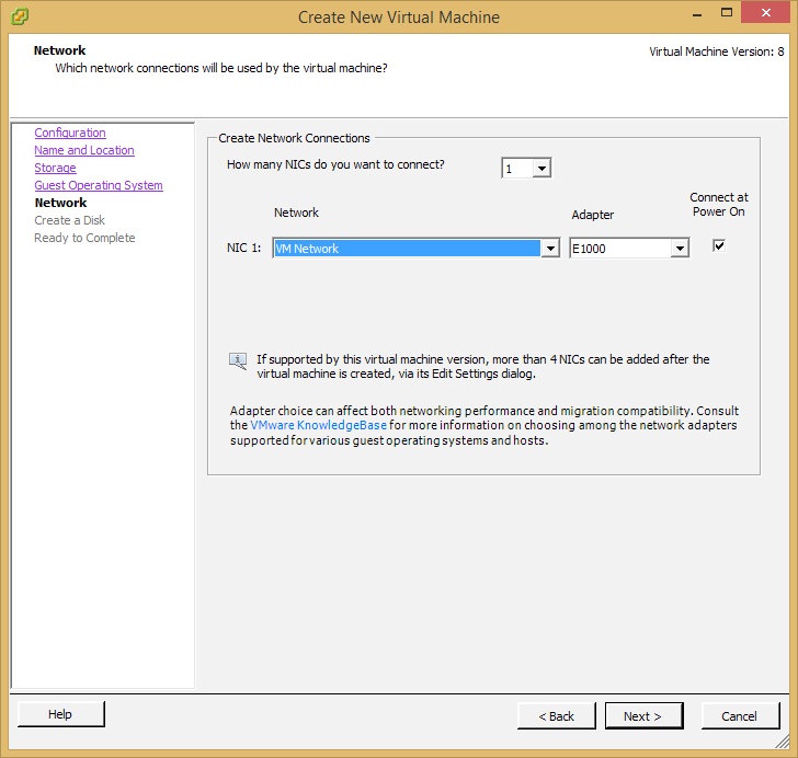
For this step, configure your NICs and click Next.
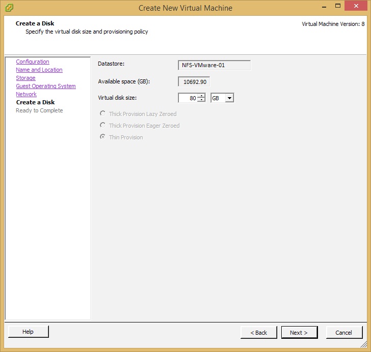
Now enter how large your virtual disk size will be and click Next. In this example we will enter 80GB.
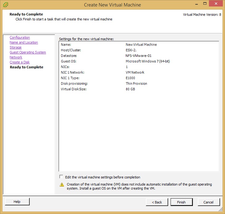
Review your VM settings and click on Finish.
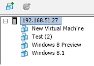
After a few seconds you will see your new virtual machine listed in an unpowered state.
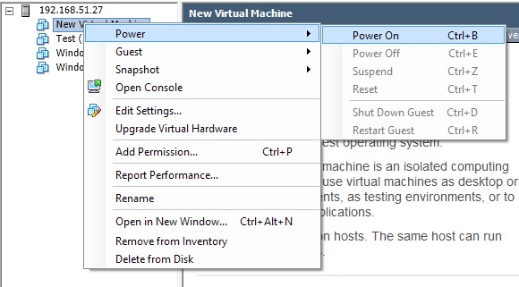
To power on the virtual machine, right click on the virtual machine icon and select Power -> Power On from the drop down menu.
Once the machine has been powered on, open a console to install the guest OS onto the VM. Click on the Launch Virtual Machine Console icon.

And that’s it! Please note that to install the OS, you will have to mount an image file of the guest OS install disc to the virtual CD/DVD drive of your virtual machine before you power it on.