

After you have defined the buildings and floors, you need to specify the following RF requirements for each floor and each supported access point model (WNAP210v2, WNAP320, WNDAP350, and WNDAP360):
- Frequency band. The radio frequency to be used (802.11b/bg/ng or 802.11a/na).
- Signal quality. The signal strength that you expect for the WLAN. This setting determines the automatic channel allocation and automatic transmission power of the access points (see the explanation in the table later in this section).
- Number of client per access point. The total number of clients that you expect to be supported on each access point.
- Total number of clients per floor. The total number of clients that you expect to be supported on each floor.
Along with the floor dimensions, these settings determine the estimated number of access points. A screen lets you visually optimize the access point locations for best coverage.
»To specify the WLAN requirements for a floor, estimate the number of access points
required, and view their suggested locations:
- Select Plans > Planning. The Planning Buildings screen displays with the Local Building tab and associated screen in view. To specify the information for a remote building, click the Remote Building tab.

The Planning Buildings screen shows a tab for each building that you previously defined. For each building, the screen shows the floors that you previously defined. - Select the building and floor that you want to configure by clicking the corresponding tabs.
- Specify the WLAN requirements for the floor as explained in the following table:
Setting Description Access Point Model Specify the access point model that you will use on the floor by selecting the WNDAP 350, WNAP 210, WNAP 320, or WNDAP 360 radio button. Frequency Band Select one of the following radio buttons to specify the frequency band that the access points will function in:
• 802.11b/bg/ng
• 802.11a/naSignal Quality Specify the required signal quality by moving the slider or by entering a percentage in the field to the right of the slider. The minimum signal quality is 25 percent; the maximum is 100 percent. Client Per Radio Specify the expected maximum number of clients per access point by moving the slider or by entering a number in the field to the right of the slider. The maximum number of clients that you can configure per access point is 64. Total Clients Specify the expected total number of clients on the floor by moving the slider or by entering a number in the field to the right of the slider. The maximum number of total clients that you can configure on the floor is 1024. - Click Estimate to view the number of access points required for the settings that you entered. The number of access points displays in a pop-up window. Access points that you
want to deploy in sentry mode are not included in this number. After you have closed the pop-up window, the Estimated Access Points row is added to the Planning Buildings screen. - Click View Map to view and optimize the suggested approximate access point locations for the settings that you entered:
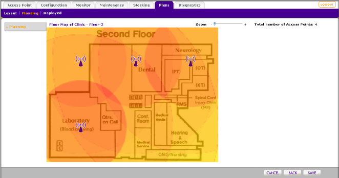
Note that the planning tool provides only default placement and shows the coverage area for each access point.
-
Move the access points to optimize coverage in desired areas and avoid coverage in unwanted areas based on the floor plan.
Colored circles around the access point symbols indicate the expected approximate coverage of the individual access point. The color of the circle represents the expected quality of the signal strength: a darker color indicates signal overlap with nearby access points.
Note:A red color indicates the strongest coverage area: better than -50 dBm RSSI; an orange color better than -60 dBm; a yellow color better than -70 dBm; and so on.
Moderate overlap is required for seamless roaming. No overlap will lead to disconnections and dead spots.
You can click an access point icon and drag it to manually reposition it to see how the new location would affect the coverage. Click Cancel to undo any access point repositioning changes.
Use the Zoom slider to increase or decrease the size of the map. - Click Save to save the location map, or click Back to return to the Planning Buildings screen without savings changes to the location map.
Note:For each floor, you can save one location map only. When you modify and save the location map, the previously saved location map is overwritten.