

The following figure shows the front and side panels of ReadyNAS 102:
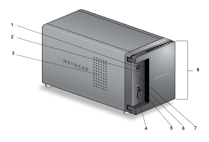
- Power button and LED
- Disk activity LED
- Exhaust vent
- USB 2.0 port
- Backup button
- USB and Backup status LED
- Disk 1 and Disk 2 LEDs
- Drive bay door
The following figure shows the drive bays of ReadyNAS 102:
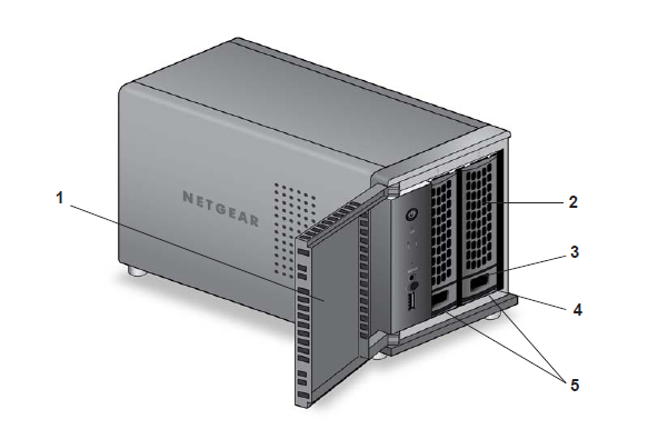
- Drive bay door
- Disk tray handle
- Recessed disk tray locking mechanism
- Disk tray release latch
- Drive bays
The following figure shows the rear panel of ReadyNAS 102:
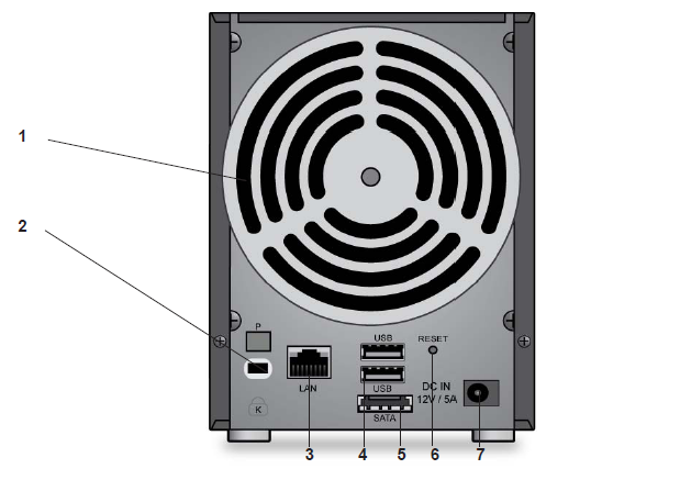
- Exhaust fan
- Kensington lock
- LAN ports with LED status indicators
- USB 3.0 ports
- eSATA port
- Reset button
- Power adapter socket
Last Updated:07/07/2025
|
Article ID: 23021