

Use the following Web interface to enable routing for ports on the switch. The default link-level encapsulation format is Ethernet. Configure the IP addresses and subnet masks for the ports. Network-directed broadcast frames will be dropped. The maximum transmission unit (MTU) size is 1500 bytes.
- Assign IP address 192.150.2.1/24 to interface 1/0/2.
- Select Routing > IP > Advanced > IP Interface Configuration.
A screen similar to the following displays.
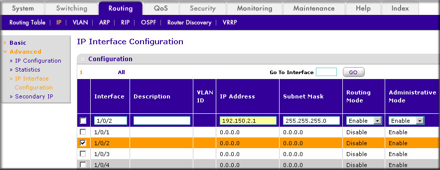
- Scroll down and select the interface 1/0/2 check box.
Now 1/0/2 appears in the Interface field at the top.
- Under the IP Interface Configuration, enter the following information:
- In the IP Address field, enter 192.150.2.1.
- In the Subnet Mask field, enter 255.255.255.0.
- In the Routing Mode field, select Enable.
- Click Apply to save the settings.
- Select Routing > IP > Advanced > IP Interface Configuration.
- Assign IP address 192.150.3.1/24 to interface 1/0/3.
- Select Routing > IP> Advanced > IP Interface Configuration.
A screen similar to the following displays.
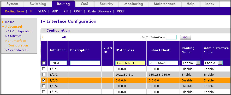
- Scroll down and select the interface 1/0/3 check box.
Now 1/0/3 appears in the Interface field at the top.
- Enter the following information:
- In the IP Address field, enter 192.150.3.1.
- In the Subnet Mask field, enter 255.255.255.0.
- In the Routing Mode field, select Enable.
- Click Apply to save the settings.
- Select Routing > IP> Advanced > IP Interface Configuration.
- Assign IP address 192.150.5.1/24 to interface 1/0/5.
- Select Routing > IP > Advanced > IP Interface Configuration.
A screen similar to the following displays.

- Scroll down and select the interface 1/0/5 check box.
Now 1/0/5 appears in the Interface field at the top.
- Enter the following information:
- In the IP Address field, enter 192.150.5.1.
- In the Subnet Mask field, enter 255.255.255.0.
- In the Routing Mode field, select Enable.
- Click Apply to save the settings.
- Select Routing > IP > Advanced > IP Interface Configuration.
For more information see the support article.
This article applies to the following managed switches and their respective firmware:
- M5300 - firmware version 10.0.0.x
-
- M5300-28G (GSM7228S)
- M5300-5G (GSM7252S)
- M5300-28G3 (GSM7328Sv2h2)
- M5300-52G3 (GSM7352Sv2h2)
- M5300-28G_POE+ (GSM7228PSv1h2)
- M5300-52G-POE+ (GSM7252PSv1h2)
- M5300-28GF3 (GSM7328FSv2)
- M4100 - firmware version 10.0.1.x
-
- M4100-26G (GSM7224v2h2)
- M4100-50G (GSM7248v2h2)
- M4100-26G-POE (GSM7226Pv1h1)
- M4100-50G-POE+ (GSM7248Pv1h1)
- M4100-26G-POE (FSM7226Pv1h1)
- M4100-50-POE (FSM7250Pv1h1)
- M4100-D12G (GSM5212v1h1)
- M4100-D10-POE (FSM5210Pv1h1)
- M7100 - firmware version 10.0.1.x
-
- M7100-24X (XSM7224)
- XSM7224S - firmware version 9.0.1.x
Last Updated:07/07/2025
|
Article ID: 21647